
Specialize in Compression molds
Specialize in Compression molds
In carbon fiber composite manufacturing, part quality depends on more than the material itself. Tool geometry, thermal behavior, machining accuracy, sealing performance and process control all influence the final component.
For automotive, transportation, industrial and other advanced composite applications, precision carbon fiber tooling provides the foundation for repeatable manufacturing. From tool design and CNC machining to trial molding and dimensional inspection, every stage must be aligned with the component's material system and production requirements.
Carbon fiber tooling refers to the molds and associated tooling systems used to manufacture carbon fiber reinforced polymer (CFRP) components. Depending on the application, the tooling may support prepreg molding, compression molding, resin transfer molding or other composite manufacturing processes.
Unlike a general-purpose mold, a carbon fiber composite tool must be designed around the specific resin system, reinforcement architecture, curing or consolidation conditions, part geometry and dimensional acceptance criteria.
The tooling may need to accommodate complex three-dimensional surfaces, controlled heating, vacuum sealing, accurate parting lines and repeatable positioning. These requirements become particularly important when the component combines tight dimensional tolerances with demanding surface-quality or structural-performance targets.
For manufacturers sourcing a carbon fiber mold or composite tooling solution, the key question is not simply whether the mold can reproduce the nominal geometry. It is whether the tooling can support the required manufacturing process and deliver consistent parts within the agreed acceptance criteria.
Carbon fiber composite parts can be sensitive to changes in temperature, material placement, resin behavior, consolidation and cooling conditions. Tooling errors or process variation may contribute to dimensional deviation, surface defects, local porosity, flash or inconsistent part-to-part results.
Precision tooling helps reduce avoidable variation by controlling the physical conditions that influence manufacturing. However, tooling accuracy alone cannot guarantee final-part accuracy. Material properties, laminate design, process settings, cure behavior and inspection methods must also be considered.
Effective carbon fiber tooling connects each manufacturing challenge with a specific engineering response and a measurable verification method. The following matrix summarizes the main factors that should be evaluated during tooling development.
| Tooling Engineering Factor | Carbon Fiber Molding Challenge | Engineering Approach | Verification Focus |
|---|---|---|---|
| Thermal Expansion and Dimensional Compensation | Differences in thermal expansion between the tool and composite component can contribute to dimensional deviation after heating, curing and cooling. | Select suitable tool materials and account for operating temperature, tool geometry, composite behavior and expected dimensional changes during the design stage. | Review critical dimensions and evaluate dimensional stability under the specified manufacturing conditions. |
| Precision CNC Machining | Complex contours, deep surfaces and demanding interfaces can make dimensional consistency difficult to maintain. | Apply suitable CNC machining strategies, including five-axis machining where required, to produce complex tool surfaces and control critical geometric features. | Inspect critical profiles, interfaces, datums and dimensions against approved tooling drawings. |
| Heating System and Thermal Uniformity | Uneven tool temperature can affect resin curing, material flow, residual stress and finished-part consistency. | Design the heating system and temperature-control strategy around the resin system, tool structure, cycle time and selected molding process. | Verify temperature distribution and process stability at defined measurement locations and operating conditions. |
| Parting Line, Venting and Vacuum Sealing | Inadequate parting-line control, venting or sealing may contribute to flash, trapped air, porosity or incomplete consolidation, depending on the process. | Engineer parting lines, shut-off surfaces, venting features and vacuum sealing arrangements according to the selected process, such as prepreg molding or HP-RTM. | Check shut-off contact, sealing performance and molded-part quality against the process requirements. |
| Tool Tryout and Dimensional Inspection | A tool that meets drawing requirements does not automatically guarantee that every molded component will meet its final-part tolerances. | Coordinate tool inspection, trial molding, process adjustment and dimensional feedback to identify the causes of deviations. | Use the inspection method specified by the customer, such as CMM measurement, 3D scanning or comparison with the approved CAD model. |
These engineering measures should be selected according to the project requirements. Specific machining tolerances, temperature-uniformity limits, sealing configurations and inspection deliverables should be confirmed against the approved drawings, process specification and quality plan.
Carbon fiber components often feature compound curves, deep profiles, mounting interfaces, ribs and other geometrically demanding features. Producing the corresponding tool surfaces requires a machining strategy that considers accessibility, rigidity, tool deflection, surface finish and dimensional inspection.
Five-axis CNC machining can help access complex surfaces from multiple orientations while reducing the need for repeated setups in suitable applications. The actual benefit depends on the component geometry, machining strategy, machine configuration and inspection requirements.
MDC has FIDIA five-axis CNC machining capability for large and complex mold manufacturing. This capability can be relevant to composite tooling projects that require carefully controlled surface geometry and coordinated machining operations.
A sound machining plan should distinguish between the nominal CAD geometry, the machined tool geometry and the final molded-part dimensions. These are related but separate quality considerations.
Where a project requires a specific tolerance, the tolerance should be assigned to the relevant feature and verified using an agreed measurement method. A single machining-accuracy figure should not be treated as a guarantee of the finished composite part's dimensional accuracy.
Temperature management is a key consideration when carbon fiber tooling is used with thermoset prepregs or other temperature-sensitive composite systems. Tool temperature affects resin viscosity, curing behavior, consolidation and dimensional changes during cooling.
If the temperature distribution is unsuitable for the selected process, the resulting component may show inconsistent cure behavior, residual stress, surface defects or dimensional variation. The appropriate solution depends on the material system and the production cycle.
Temperature limits should be established from the resin supplier's recommendations, process requirements and project validation data. A stated temperature-uniformity value is meaningful only when the measurement locations, operating conditions and acceptance criteria are defined.
Parting-line design and sealing requirements vary with the carbon fiber molding process. Prepreg molding, compression molding and high-pressure resin transfer molding do not necessarily use the same sealing arrangement or operate under the same pressure conditions.
A tooling solution must therefore be developed around the actual process rather than applying one universal sealing design to every carbon fiber component.
During tooling validation, sealing performance, parting-line condition and molded-part quality should be checked against the selected process specification. Any numerical gap, shut-off tolerance or vacuum acceptance limit should be defined for the specific tool and process.
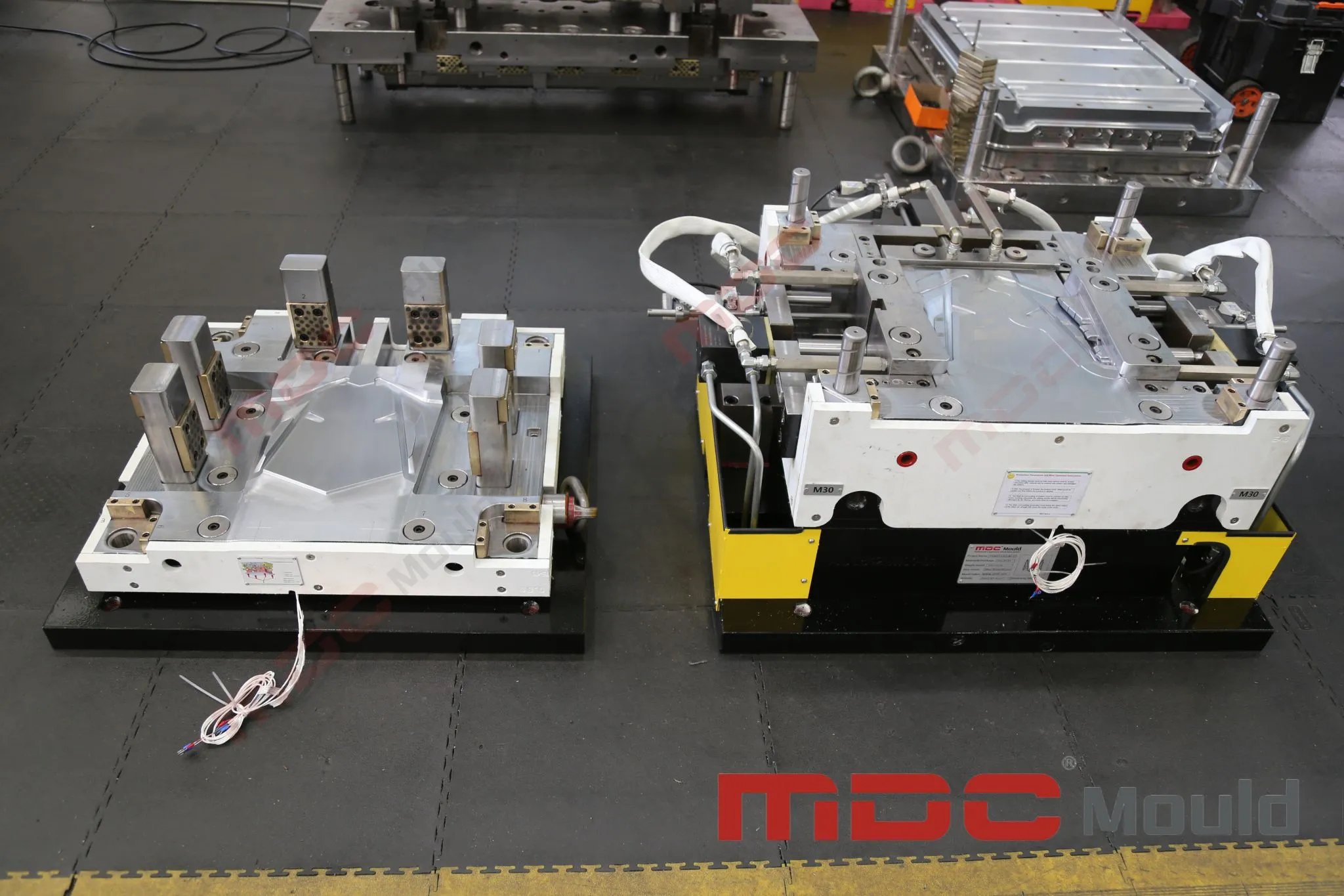
Precision machining is one stage in the tooling lifecycle. Before a carbon fiber mold is released for production, the manufacturing team and customer may need to review tool dimensions, functional interfaces, process readiness and the results of trial molding.
A structured validation process helps distinguish tooling issues from material or process issues. For example, a dimensional deviation in a molded part may result from tool geometry, thermal expansion, laminate behavior, curing conditions or the interaction of several factors.
Trial molding should be treated as a validation activity, not simply a demonstration that the mold can close and produce a part. Its purpose is to evaluate the relationship between the tool, material and process under defined conditions.
Dimensional inspection provides evidence that tooling or molded components meet specified requirements. The appropriate measurement method depends on the part size, geometry, tolerance, material behavior and inspection plan.
Coordinate measuring machines (CMMs) can be used to measure defined dimensions and geometric features. 3D scanning can support the evaluation of complex surfaces by comparing captured geometry with an approved CAD reference. Depending on the application, these methods may complement rather than replace one another.
A 3D color map or point-cloud comparison can make surface deviations easier to interpret, but its usefulness depends on a suitable measurement process and correct alignment with the reference model. The report should clearly identify the measured object and the criteria used for acceptance.
CMM measurement, 3D scanning and first-article documentation should be confirmed during project quotation. They should not be assumed to be included in every tooling order unless the scope of supply states so.
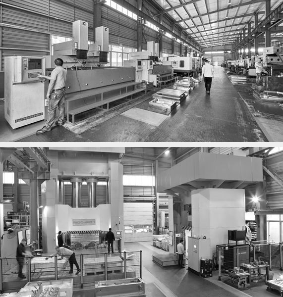
Selecting a carbon fiber tooling manufacturer requires an assessment of engineering capability, manufacturing resources, quality systems and project communication. A supplier's machine list is useful, but it does not by itself establish that the supplier can meet a particular component's requirements.
Buyers should evaluate the manufacturer's capabilities against the actual part geometry, tool size, molding process, dimensional requirements and production plan.
MDC's FIDIA five-axis CNC machining capability supports the manufacture of large and complex molds. For any specific carbon fiber tooling project, the suitable machine, tooling configuration, inspection method and validation scope should be reviewed against the customer's technical requirements.
A complete request for quotation (RFQ) helps a tooling manufacturer assess technical feasibility, define the scope of supply and prepare a more accurate quotation. Missing material or process information can lead to assumptions that affect tool design, lead time and cost.
To help MDC evaluate a carbon fiber tooling project, buyers should prepare the following information where available:
With these inputs, MDC can review the project requirements and determine which tooling design, machining and validation arrangements are appropriate.
Carbon fiber tooling refers to molds and related tooling systems used to manufacture carbon fiber composite components. Tooling requirements depend on the material, manufacturing process, component geometry and specified production tolerances.
Precision machining helps control tool geometry, surface profiles, parting-line alignment and critical interfaces. These factors support repeatable production, although final-part accuracy also depends on material behavior and process control.
No. Five-axis CNC machining can improve access to complex surfaces and reduce certain setup-related errors, but finished-part accuracy also depends on tool design, material behavior, thermal conditions, molding parameters and inspection.
Temperature influences resin curing, material flow, thermal expansion and dimensional changes during cooling. The heating and temperature-control strategy should be developed for the selected material system and molding process.
Verification may include dimensional inspection, critical-surface checks, parting-line evaluation, functional testing and trial molding. CMM measurement or 3D scanning may be used when specified by the project inspection plan.
MDC has FIDIA five-axis CNC machining capability for large and complex mold manufacturing. The feasibility of a specific carbon fiber tooling project should be confirmed based on the mold dimensions, weight, material, machining requirements and validation scope.
Provide the latest 3D CAD model, 2D drawings, composite material specifications, molding process, target production volume, critical tolerances, surface requirements and inspection expectations. Equipment limitations and the target project schedule are also useful.
Reliable carbon fiber tooling combines engineering design, appropriate machining methods, process-specific thermal and sealing solutions, and documented quality verification. Each of these elements should be considered in relation to the actual component and its production requirements.
MDC supports industrial mold manufacturing with engineering coordination and FIDIA five-axis CNC machining capability. If you are developing a new carbon fiber composite component or evaluating tooling for an existing production program, share your drawings and process requirements for a project-specific review.
Contact MDC: master@zjmdc.com
Website: MDC Mould
Contact US
Email: master@zjmdc.com
Tel: +86 576 84616076
Fax: +86 576 84616079
Mobile: +86 13906573507(Mr. Wang)
Address: No.116 mochuang road, Huangyan Xinqian street,Taizhou,Zhejiang,China