
Specialize in Compression molds
Specialize in Compression molds
Composite compression molding is widely used for manufacturing structural, automotive, electrical, transportation, agricultural, and industrial composite components. However, stable compression molding production depends on much more than applying heat and pressure to a material charge.
The final part is influenced by the interaction between material behavior, charge placement, mold temperature, pressure, closing speed, venting, shear-edge design, tooling accuracy, mold rigidity, and press capability.
For this reason, composite compression molding should be treated as an integrated manufacturing system rather than simply a mold-closing operation.
MDC approaches compression tooling from this process-oriented perspective. The objective is to develop tooling that supports predictable material flow, controlled thermal behavior, effective air evacuation, accurate edge control, dimensional stability, and repeatable production.
Composite compression molding is a manufacturing process in which a composite material is placed into or onto a mold cavity and formed under controlled pressure and temperature.
Depending on the material system, the process can involve thermoset curing or thermoplastic melting and consolidation. Common composite materials used with compression molding include SMC, BMC, GMT, LFT, carbon-fiber composites, and other reinforced thermoset or thermoplastic materials.
Although the basic principle is straightforward, industrial production requires close coordination between the material, mold, and press.
The quality of the final composite part is therefore determined by the combined behavior of these three systems.
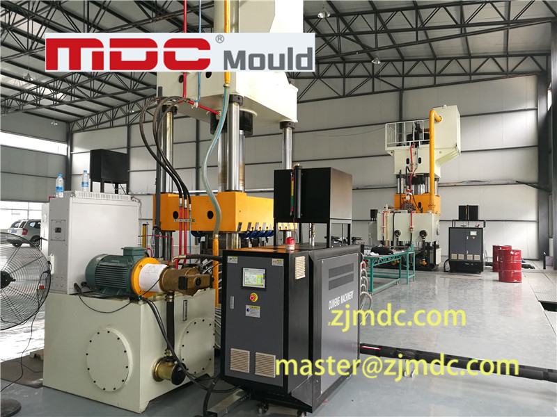
A compression mold is not an independent component of the manufacturing process. Its geometry directly affects how the material moves, how air escapes, how heat is transferred, and how pressure is distributed.
For example, an uneven mold temperature can produce different material viscosities across the cavity. This can change the filling behavior and contribute to uneven shrinkage or warpage.
Similarly, insufficient venting can trap air as material fronts converge. Excessive shear-edge clearance may increase flash, while insufficient clearance can increase fiber damage or tooling interference.
This creates a direct engineering relationship:
Material behavior → Process condition → Mold response → Part quality → Production stability
MDC therefore evaluates compression tooling from both the mechanical and process perspectives.
The following matrix summarizes several important relationships between compression molding process control, common defects, and tooling engineering solutions. Actual specifications are determined according to part geometry, material formulation, reinforcement content, production volume, press characteristics, and project requirements.
| Process Pillar | Common Defect | MDC Tooling Solutions |
|---|---|---|
|
Thermal Control Mold Temperature Balance |
Large mold-surface temperature differences can contribute to warpage, uneven shrinkage, inconsistent curing, and dimensional variation. | Optimized oil-heating channel layouts and deep-hole heating circuits can be designed according to the mold structure. For applicable tooling projects, mold-surface temperature variation can be controlled to approximately ±1.0°C, subject to the specific mold and process requirements. |
|
Shear Edge Clearance Edge Matching |
Excessive flash, fiber tearing, fiber pull-out, or local mold interference around shear-edge areas. | Precision fitting of vertical shear edges is used to control material escape and improve edge consistency. For applicable projects, clearance may be engineered within approximately 0.02 mm–0.04 mm according to material, part geometry, and tooling requirements. |
|
Venting & Void Control Air Evacuation |
Entrapped air, burn marks, local short shots, internal voids, and incomplete material filling. | Multi-stage stepped venting channels can be incorporated into the mold design. Critical areas can also be evaluated for vacuum-assisted venting when conventional venting cannot provide sufficient air evacuation. |
|
Pressure & Degassing Press Movement Control |
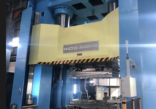
Internal porosity, incomplete degassing, uneven glass-fiber distribution, or inconsistent consolidation. | The mold can be coordinated with the hydraulic press to support controlled micro-opening / degassing stroke sequences. For suitable applications, press capacity such as a 4000-ton compression press can be incorporated into the process-development strategy. |
|
Tooling Longevity Wear Resistance |
Mold-cavity wear caused by high-glass-content materials such as SMC and GMT, potentially affecting dimensional stability and surface quality over production cycles. | Wear-critical components can use hardened tool steel such as H13 / 1.2344. Where specified by the application, hardened material and surface treatment can be selected to improve resistance to abrasive composite materials, with approximately HRC 48–52 hardness and a hard-chrome layer around 0.03 mm for applicable project specifications. |
This matrix provides a practical way to connect a visible molding defect with the process variable and tooling feature that should be investigated. Instead of treating each defect independently, engineers can use the relationship between process condition, material behavior, and mold design to identify the underlying cause.
Material flow is one of the most important variables in compression molding. When the mold closes, the material charge spreads through the cavity under pressure.
The resulting flow pattern depends on:
If material flow is poorly controlled, several defects can appear even when the final mold dimensions are accurate.
Potential problems include fiber movement, local resin-rich areas, incomplete filling, weld-like flow interfaces, voids, surface variation, and dimensional instability.
This is why compression mold design should consider the expected flow path before machining is completed.
The initial position and shape of the material charge can strongly influence the way a composite fills the mold cavity.
A charge that is too small may result in incomplete filling. A charge that is too large can increase flash or require excessive material movement. An inappropriate charge position can also cause an unbalanced flow front.
For complex components, charge placement should therefore be considered together with:
A tooling supplier that understands these interactions can identify potential flow-related problems earlier in the design stage.
Temperature control is a critical part of composite compression molding because the mold performs both a forming function and a thermal-management function.
For thermoset composites, temperature influences resin viscosity and curing behavior. For thermoplastic composites, temperature affects melting, consolidation, and material mobility.
The important engineering objective is therefore not simply to specify a single mold temperature. It is to establish a sufficiently uniform and repeatable thermal field across the functional areas of the tooling.
Heating channels that are poorly positioned can create local hot spots and cold areas. Differences in thermal mass around inserts, ribs, deep cavities, and thick mold sections can further increase thermal variation.
MDC evaluates the heating-channel arrangement according to mold geometry and thermal requirements. Oil heating systems and deep-hole circuits can be arranged to improve heat distribution where applicable.
For projects requiring tight thermal control, the target should be established through engineering analysis and trial validation rather than assumed from a single machine setpoint.
Compression molding requires sufficient pressure to consolidate the material and reproduce the cavity geometry. However, simply increasing pressure does not automatically improve part quality.
Excessive or poorly timed pressure can influence material movement, flash, fiber orientation, mold loading, and equipment requirements.
Closing speed also matters because the material needs to flow while air is being displaced from the cavity.
A suitable process window should therefore consider:
The mold design must support the required sequence instead of assuming that pressure alone will compensate for poor flow or venting.
Air trapped inside the mold cavity can become a major source of composite part defects.
During mold closing, the material progressively occupies the cavity. If the air cannot escape through an appropriate path, it may become trapped between flow fronts or inside local geometric features.
Typical symptoms include:
A compression mold may require more than one simple venting groove. Depending on the part geometry, stepped or multi-stage venting can provide controlled air evacuation while limiting unwanted material escape.
Vent locations should be evaluated according to the expected material-flow front and the areas where air is most likely to accumulate.
For particularly challenging geometries, vacuum-assisted venting can be considered as an additional process tool.
Its application depends on the material system, cavity configuration, surface requirements, production cycle, and expected air evacuation behavior.
The important principle is that venting should be designed around material flow rather than added as an afterthought.
Some composite compression molding applications benefit from controlled degassing during the molding cycle.
A controlled micro-opening movement can temporarily create an escape path for trapped air before final consolidation. The timing and stroke must be coordinated with material viscosity, mold temperature, pressure, and charge placement.
This means that a degassing stroke is not simply a press parameter. The mold must also be designed to tolerate the required movement while maintaining alignment, edge control, and final dimensional accuracy.
MDC can consider the relationship between mold structure and press movement during tooling development, particularly for large composite components where air evacuation and consolidation can be challenging.
Flash is a common issue in compression molding, but excessive flash should not automatically be treated as a material problem.
The parting line, shear edge, mold matching, cavity pressure, material charge, and closing conditions can all influence how much material escapes from the cavity.
A properly engineered shear edge provides a controlled interface between the forming region and excess material.
If the clearance is too large, excessive flash may be generated. If it is too small, the mold can experience excessive interference and may damage fibers or increase local wear.
For suitable tooling projects, MDC can precision-fit vertical shear edges to tight project-specific requirements. A clearance range around 0.02 mm–0.04 mm may be specified for applicable applications, but the correct value must be determined from the material, part geometry, mold structure, and production requirements.
SMC and GMT can contain significant amounts of glass fiber reinforcement. Repeated production cycles can therefore expose mold surfaces to abrasive wear.
Tool steel selection should consider:
H13 / 1.2344 hardened tool steel can be considered for wear-critical components. Depending on the project, heat treatment and surface treatment may be applied to improve resistance to abrasive composite materials.
A typical project specification may include approximately HRC 48–52 hardness and a hard-chrome layer around 0.03 mm, subject to the actual tooling design and customer requirements.
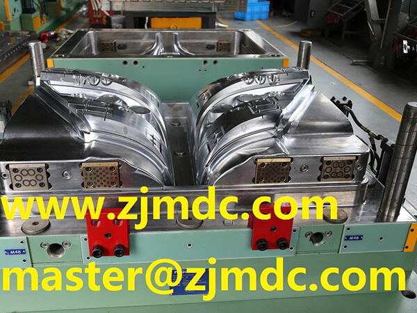
The mold geometry must reproduce the final part while also allowing the material to flow, the air to escape, the heat to transfer, and the finished part to be removed.
Important design areas include:
Each of these features can affect production performance. Therefore, compression mold optimization should be performed as a complete system rather than by optimizing one geometric feature at a time.
| Material or Process Condition | Possible Result | Tooling Consideration |
|---|---|---|
| High material viscosity | Longer filling time or incomplete filling | Temperature distribution, flow path, charge placement |
| Unbalanced charge position | Uneven flow fronts | Charge strategy, cavity geometry, venting |
| Complex ribs and deep features | Local air trapping or filling difficulty | Local venting and material-flow analysis |
| Uneven mold temperature | Different material behavior across the cavity | Heating-channel arrangement and thermal balance |
| Excessive pressure | Flash, material displacement, unnecessary mold loading | Pressure distribution and shear-edge design |
| High glass-fiber content | Increased tooling wear | Tool steel, hardness, surface treatment |
SMC compression molding is widely used for industrial composite components because it can combine relatively high production efficiency with complex geometry and repeatable dimensional control.
However, the material contains chopped reinforcement and resin, so its flow behavior is affected by charge geometry, temperature, pressure, and cavity shape.
The compression mold must therefore support:
This is why SMC tooling should be developed together with an understanding of the material's actual production behavior.
BMC is also commonly processed through compression molding, but its material form and flow behavior differ from SMC.
BMC is typically handled as a bulk molding compound, which changes the way material placement, flow, venting, and cavity filling should be considered.
A tooling concept developed for one composite material should therefore not automatically be transferred to another material without process evaluation.
The same principle applies to GMT, LFT, carbon-fiber composites, and other reinforced materials. Tooling geometry must be compatible with the material's specific processing behavior.
Large compression molds introduce additional mechanical and thermal considerations.
As mold size increases, maintaining uniform temperature becomes more challenging. Mold weight increases, machining becomes more demanding, and structural rigidity becomes increasingly important.
Large-format tooling must therefore be evaluated in terms of:
For large compression molds, the manufacturing process itself becomes part of the engineering challenge.
Compression molding process optimization should follow a structured approach rather than changing multiple variables randomly during production trials.
Identify the material family, reinforcement type, fiber content, processing temperature, viscosity behavior, cure or consolidation characteristics, and required surface quality.
Identify thin sections, thick sections, ribs, bosses, deep features, intersections, sharp transitions, and potential air-trapping areas.
Determine the appropriate charge size, shape, number of charge pieces, and initial placement based on the expected filling behavior.
Design heating channels around the cavity geometry and required process temperature. Avoid relying solely on a machine setpoint without evaluating actual mold-surface temperature distribution.
Determine where air is likely to accumulate and provide suitable venting paths. For difficult geometries, evaluate stepped venting or vacuum-assisted solutions.
Define the relationship between closing speed, pressure build-up, degassing, final consolidation, and curing or cooling.
Use trial molding to verify filling behavior, flash, surface quality, dimensional accuracy, temperature distribution, and production repeatability.
Modern compression molding increasingly depends on process data rather than operator experience alone.
Important parameters can include:
When process data is connected with tooling design, recurring defects can be investigated more systematically.
For example, if a dimensional variation repeatedly appears in the same location, engineers can compare the defect location with the local heating circuit, cavity stiffness, pressure distribution, or material-flow path.
High machining accuracy is important, but precision alone does not guarantee production stability.
A mold can meet CAD dimensions and still experience production problems if:
The practical goal is therefore to combine geometric accuracy with process functionality.
Composite compression molding can be applied to a wide range of industrial components where weight, dimensional stability, mechanical performance, surface quality, corrosion resistance, electrical insulation, or production efficiency are important.
Typical application areas include:
The appropriate compression molding process depends on the material, geometry, production volume, performance requirements, and available press equipment.
A production-ready compression mold should satisfy more than dimensional inspection requirements.
A complete tooling evaluation should consider:
| Evaluation Area | Key Question |
|---|---|
| Dimensional Accuracy | Does the cavity reproduce the required part geometry and tolerances? |
| Thermal Performance | Can the mold maintain the required temperature distribution? |
| Material Flow | Does the cavity support predictable filling behavior? |
| Venting | Can trapped air escape without excessive material loss? |
| Shear Edge | Can flash be controlled without damaging the material or mold? |
| Structural Rigidity | Can the mold maintain geometry under production pressure? |
| Wear Resistance | Can critical surfaces withstand the expected production cycles? |
| Demolding | Can the finished component be removed without surface or dimensional damage? |
MDC develops composite compression tooling around the relationship between part geometry, material behavior, mold structure, thermal control, and press conditions.
The goal is to ensure that the mold is not only accurate as a manufactured component, but also functional as part of the complete production system.
MDC's manufacturing capabilities include FIDIA five-axis CNC machining for complex and large-format tooling. For suitable projects, machining capability can reach approximately 6 × 4 meters.
Large and heavy tooling also requires appropriate handling, assembly, inspection, and production planning. These factors are considered during tooling development rather than being treated only as post-machining activities.
The overall workflow can include:
For an accurate tooling proposal, a compression mold manufacturer should receive more than a 3D CAD model.
Important project information includes:
The more accurately these inputs are defined, the more effectively the tooling design can be developed around the actual production process.
| Observed Problem | Potential Cause | Engineering Direction |
|---|---|---|
| Warpage | Uneven temperature, shrinkage, pressure distribution, or mold deflection | Review thermal balance, mold stiffness, material flow, and process parameters |
| Excessive Flash | Parting-line clearance, shear-edge design, charge volume, pressure | Review shear-edge geometry and material containment |
| Fiber Pull-Out | Improper shear-edge interaction or excessive mechanical interference | Review edge clearance and local tooling geometry |
| Burn Marks | Trapped air and inadequate venting | Review vent location, vent depth, and air evacuation strategy |
| Internal Voids | Incomplete degassing or unfavorable flow-front convergence | Review charge placement, venting, pressure sequence, and degassing |
| Uneven Surface Quality | Temperature variation, material distribution, mold surface condition | Review thermal system, cavity finish, material flow, and tooling condition |
| Dimensional Variation | Thermal instability, mold deflection, inconsistent process conditions | Review mold rigidity, thermal balance, pressure, and process repeatability |
| Accelerated Tool Wear | High glass-fiber content and repeated production cycles | Review steel grade, hardness, surface treatment, and replaceable wear components |
The development of composite compression molding is increasingly focused on process integration rather than simply increasing press force or machining accuracy.
Future tooling development is expected to place greater emphasis on:
As composite applications become more demanding, mold manufacturers need to consider not only how accurately a mold can be machined, but also how effectively it can control the complete molding process.
Composite compression molding is a manufacturing process in which composite materials are formed under controlled heat and pressure inside a mold. It is used with materials such as SMC, BMC, GMT, LFT, and other reinforced composite systems.
Mold temperature affects material viscosity, flow, curing or consolidation, surface quality, and dimensional stability. Uneven temperature distribution can result in different material behavior across the same component.
Venting provides an escape path for air and volatile components during mold closing. Poor venting can contribute to trapped air, voids, burn marks, surface defects, and incomplete filling.
A shear edge is a controlled tooling feature used to manage excess material and flash around selected areas of a compression-molded component. Its clearance must be matched to the material, part geometry, and production requirements.
Yes. Vacuum-assisted venting can be considered for SMC applications where conventional venting does not provide sufficient air evacuation. Its application depends on part geometry, material behavior, cavity configuration, and production requirements.
Hardened tool steels such as H13 / 1.2344 can be considered for wear-critical mold components. Steel grade, hardness, heat treatment, and surface treatment should be selected according to material composition, production volume, expected wear, and tooling-life requirements.
Defect reduction normally requires a combined review of material preparation, charge placement, mold temperature, pressure, closing speed, venting, shear edge design, mold rigidity, and tooling accuracy. Changing only one process parameter may not address the actual root cause.
Mold geometry determines the available flow paths, cavity restrictions, pressure distribution, venting locations, and material containment. Therefore, part geometry and tooling design directly influence how a composite material fills the cavity.
Important information includes the part CAD data, material specification, reinforcement content, production volume, cycle-time target, press specification, temperature requirements, surface requirements, dimensional tolerances, tooling-life expectations, and any special requirements for venting, vacuum, trimming, or inserts.
Composite compression molding is a process in which material behavior, thermal management, pressure control, venting, and tooling geometry interact continuously.
A production-oriented compression mold therefore needs to provide more than accurate cavity dimensions. It should support predictable material flow, stable thermal behavior, effective air evacuation, controlled flash, sufficient structural rigidity, and appropriate resistance to long-term wear.
The engineering relationship can be summarized as:
Material → Flow → Temperature → Pressure → Venting → Tooling → Part Quality → Production Stability
MDC applies this integrated approach to composite compression tooling, combining tooling engineering, precision CNC machining, mold construction, process consideration, and trial validation to support demanding industrial compression molding applications.
Contact US
Email: master@zjmdc.com
Tel: +86 576 84616076
Fax: +86 576 84616079
Mobile: +86 13906573507(Mr. Wang)
Address: No.116 mochuang road, Huangyan Xinqian street,Taizhou,Zhejiang,China