
Specialize in Compression molds
Specialize in Compression molds
Automotive roof components can involve large surface areas, curved profiles and product-specific geometric details. Turning these designs into reliable production tooling requires careful coordination between mould engineering, machining and final assembly.
At MDC Mould, a roof component tooling project provides an example of how attention to detail runs through the manufacturing process. From mould design to machining and final assembly, each stage contributes to the consistency and usability of the finished tooling.
This article examines the key manufacturing considerations behind automotive roof component compression moulds and explains what buyers and engineering teams should review when developing similar tooling.
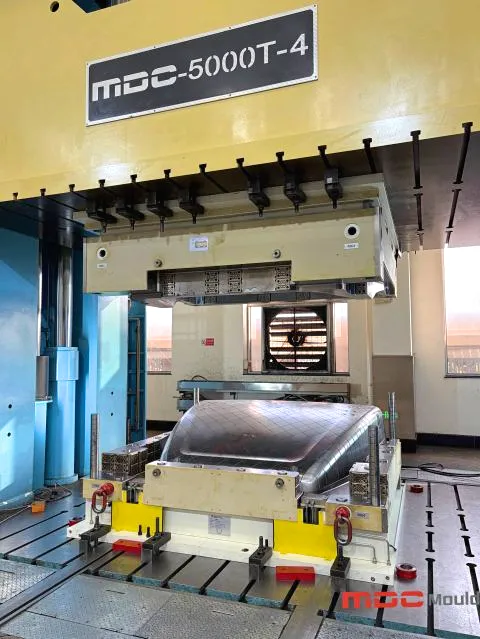
Automotive roof components are not simply flat panels. Depending on the vehicle design and component function, they may include curved surfaces, transitions between different profiles, local recesses, mounting features and detailed edge geometries.
These features influence how the mould needs to be designed and manufactured. A tooling project must translate the component's digital geometry into physical mould surfaces and functional structures that can be assembled and operated as intended.
Several aspects deserve particular attention:
These considerations should be reviewed together rather than treated as isolated design tasks. A change to one local feature may affect the surrounding mould geometry, machining strategy or assembly arrangement.
The first major task in a roof component tooling project is understanding the product data. The mould design must reflect the intended component geometry while accounting for the requirements of the selected molding process.
Large roof-related components may contain broad curved surfaces and transitions between different geometric regions. These areas need to be reviewed carefully during the design stage.
Engineering review may focus on:
The objective is to establish a clear relationship between the product model and the mould surfaces before manufacturing begins.
Once the product geometry has been reviewed, the mould structure can be developed around the required forming surfaces and operating conditions.
Depending on the component and process, the design review may include:
These decisions influence more than the initial mould layout. They also affect how individual components can be machined, fitted and maintained throughout the tooling's service life.
A mould design should be reviewed for manufacturability before machining data is released. This helps identify potential problems such as difficult tool access, insufficient space for machining operations or features that may complicate final assembly.
For automotive roof component tooling, this review is particularly useful around curved transitions, edge details and interfaces between different mould sections.
After the mould design has been prepared, machining turns the engineering data into physical tooling components. The quality of this stage depends on the relationship between the digital model, machining strategy, equipment setup and inspection process.
Complex roof component surfaces may contain continuously changing curvature and local transitions. The machining process needs to follow the intended geometry while taking account of tool accessibility and the selected machining sequence.
Important considerations include:
A machining process should not be evaluated only by how quickly material is removed. The resulting surface geometry, dimensional condition and suitability for subsequent fitting are equally important.
Surface transitions can be particularly sensitive areas in mould manufacturing. Changes in curvature, narrow features and local recesses may require different machining approaches.
If these areas are not considered carefully, additional fitting or correction work may be required later. Reviewing the machined geometry against the approved design data helps identify deviations before final assembly.
Accurate machining provides the foundation for final mould fitting, but it does not independently guarantee that the complete tool will perform as intended.
The interfaces between mould components, alignment features, parting surfaces and assembly conditions must also be checked. This is why machining and fitting should be treated as connected stages of the same manufacturing process.
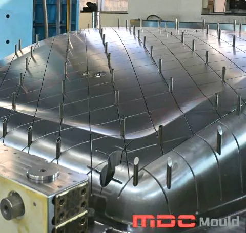
Once the individual mould components have been machined and prepared, fitting and assembly become central to the project.
A mould may contain accurately machined individual parts, but the complete assembly still needs to be checked as an integrated tooling system. The purpose of fitting is to confirm that the relevant components work together according to the design requirements.
The relationship between the upper and lower mould components is an important part of compression mould construction.
Assembly checks may cover:
The specific inspection points and acceptance criteria should be established from the mould design and project specifications.
Parting surfaces are important interfaces in compression mould tooling. Their condition can influence mould closure and the formation of the component's edge regions.
During fitting, relevant contact areas and interfaces should be examined against the agreed technical requirements. Any adjustment should be controlled so that corrections do not introduce unwanted changes to surrounding surfaces or dimensions.
Assembly quality should also be considered from a longer-term production perspective. Areas that require inspection, cleaning, adjustment or maintenance should be accessible where the design allows.
A well-considered mould structure makes it easier for production and maintenance teams to understand the tooling and carry out routine checks.
In large automotive tooling projects, attention is often focused on overall mould dimensions and major forming surfaces. However, smaller details can also influence the finished tool's usability and the consistency of subsequent production.
A local deviation in a forming surface may affect the corresponding region of the molded component. The importance of the deviation depends on its location, magnitude and the component's specified requirements.
Critical surfaces should therefore be inspected using suitable measurement methods and compared with the approved product and mould data.
The parting line and surrounding edge geometry need to be consistent with the intended component design. Poorly controlled interfaces may lead to additional finishing work or create difficulties during production.
These areas deserve attention during both design review and final mould fitting.
Mould alignment is not simply an assembly issue. It is also related to the repeatability of the mould's opening and closing movement. Locating features, guiding arrangements and mating surfaces should be checked as part of the completed tooling.
Approved drawings, revision records and inspection requirements help maintain consistency between design, machining and assembly. Clear documentation is especially important when a project involves multiple mould components or design revisions.
For automotive suppliers and tooling buyers, mould approval should involve more than a visual review of the assembled tool. The inspection process should be based on the agreed technical requirements and intended production conditions.
The following checklist can help structure a tooling review:
| Review Area | What to Check |
|---|---|
| Product Data | Confirm that the mould is based on the latest approved product drawings and CAD data. |
| Forming Surfaces | Review critical surface geometry and specified dimensional requirements. |
| Parting Line | Check the relevant parting line arrangement and interface condition. |
| Mould Alignment | Review the positioning and guiding relationship between mould components. |
| Opening and Closing | Check the mould's movement and relevant mechanical interfaces. |
| Inspection Records | Confirm that required measurements and inspection results are documented. |
| Production Requirements | Review whether the agreed trial and acceptance criteria have been addressed. |
| Maintenance | Check access to relevant areas for inspection and routine maintenance. |
The exact acceptance procedure should be agreed before the project reaches the final inspection stage. This helps ensure that the manufacturer and buyer are working toward the same technical expectations.
A closer look at MDC Mould's roof component tooling project highlights an important principle in composite mould manufacturing: good tooling starts with getting the details right.
The project involved a coordinated manufacturing process covering mould design, machining and final assembly. Each stage played a role in turning the tooling design into a completed mould.
Rather than treating machining and assembly as separate activities, the manufacturing process requires attention to how each stage connects with the next. Design decisions influence machining; machining results affect fitting; and final assembly brings the individual components together as a complete tool.
This project reflects MDC Mould's approach to composite tooling: careful attention to manufacturing details throughout the process, rather than focusing on a single production operation.
For automotive roof component tooling, this coordinated approach provides a practical foundation for preparing moulds for their intended production applications.
A clear technical brief helps the mould manufacturer understand the component and evaluate the tooling requirements at an early stage. Buyers developing a new roof component mould should prepare the following information where available:
If the product design is still under development, preliminary CAD data and a description of the intended application can provide a starting point for an initial tooling discussion.
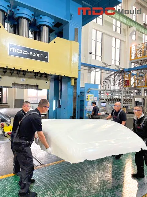
Automotive roof component tooling involves the interaction of product geometry, mould construction, machining and assembly. Selecting a mould manufacturer should therefore involve evaluating its engineering communication and manufacturing execution, not simply comparing quotations.
Buyers should look for a supplier that can:
MDC Mould manufactures composite tooling and supports projects involving mould design, machining and assembly. The company's experience across these stages provides a basis for discussing automotive and other industrial composite mould requirements.
It is a production tool used to form a roof-related automotive component through a compression molding process. Its configuration depends on the component geometry, material system and production requirements.
The manufacturer generally needs the latest product drawings, 3D CAD data, material information, dimensional requirements, production volume and relevant molding equipment specifications.
Roof-related components may contain broad curved surfaces and transitions between different geometric regions. These features need to be represented accurately in the mould design and manufacturing data to meet the agreed component requirements.
Machining produces individual mould components, but final fitting checks how those components work together. Alignment, parting surface contact and opening and closing movement are among the areas that may need to be reviewed.
Buyers should review the approved product data, forming surfaces, parting line, mould alignment, opening and closing movement, inspection records and agreed production acceptance requirements.
Yes. MDC Mould manufactures composite moulds and has experience with automotive and industrial tooling applications. Project feasibility and the appropriate manufacturing route should be evaluated against the specific component data and requirements.
Developing an automotive roof component mould requires careful coordination between product geometry, mould design, machining and final assembly.
If you are planning a new roof component tooling project, MDC Mould welcomes technical discussions based on your product drawings, 3D CAD data and production requirements.
Share your component information and let us review the key tooling considerations with you.
Contact MDC Mould: master@zjmdc.com
For large automotive roof panels requiring heavy-duty tooling, five-axis surface machining, and high-tonnage press validation, learn more about our large SMC mould manufacturing and 4000T press capabilities.
Contact US
Email: master@zjmdc.com
Tel: +86 576 84616076
Fax: +86 576 84616079
Mobile: +86 13906573507(Mr. Wang)
Address: No.116 mochuang road, Huangyan Xinqian street,Taizhou,Zhejiang,China