
Specialize in Compression molds
Specialize in Compression molds
A composite mold is one of the most important components in composite manufacturing. The mold determines the final geometry of the part while also influencing dimensional accuracy, surface quality, material flow, curing behavior, demoulding, and production repeatability.
Unlike a simple forming tool, composite tooling must be designed around the specific material and molding process being used. Carbon fiber composites, SMC, BMC, FRP, and other composite materials can have different flow characteristics, curing requirements, pressure conditions, and temperature requirements.
At MDC, we manufacture customized composite molds and composite tooling for a wide range of industrial applications. Our tooling solutions are developed according to product geometry, composite material, molding process, production volume, equipment conditions, and required surface quality.
A composite mold is a precision tooling system used to form composite materials into a defined product geometry. Depending on the application, composite molds can be used with processes such as compression molding, prepreg molding, RTM, vacuum-assisted processes, and other composite manufacturing methods.
The mold normally consists of one or more forming surfaces together with structural supports, heating components, venting features, locating elements, inserts, and other tooling components required by the production process.
The basic function is straightforward: the mold provides the geometry and surface against which the composite material is formed or cured.
However, achieving stable production requires much more than simply reproducing the product shape. A production-oriented composite mould must also consider:
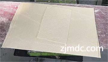
Composite parts often contain complex curves, ribs, bosses, deep sections, varying wall thicknesses, or large cosmetic surfaces. These features can create specific challenges during forming and curing.
A well-designed composite mold helps control these challenges by providing a stable and accurately manufactured forming surface.
Poor tooling design can contribute to:
For this reason, mold design should begin with an understanding of the complete manufacturing process rather than being treated as a separate machining task.
There is no single mold structure suitable for every composite application. The correct tooling configuration depends on the material, forming method, product geometry, production volume, and required performance.
Carbon fiber components may be manufactured using prepreg, compression molding, autoclave, RTM, or other processes. The tooling must be designed according to the selected material system and curing process.
For applications requiring high-quality cosmetic surfaces, cavity accuracy and surface finishing become particularly important because the mold surface can directly influence the finished carbon fiber component.
SMC molds are commonly used for compression molding applications. The tooling must accommodate material flow, molding pressure, curing temperature, flash control, venting, and demoulding requirements.
For large SMC components, mould rigidity and thermal distribution are especially important for maintaining consistent production results.
BMC molding also requires tooling designed around thermoset material behavior. Cavity geometry, temperature control, venting, surface finish, and parting-line accuracy can all influence the final molded component.
FRP and other reinforced composite materials may use different forming and curing processes. The mould structure should therefore be adapted to the selected manufacturing method, material system, and production requirements.
A production-ready composite mold typically consists of several interconnected engineering features. Each component contributes to the performance of the overall tooling system.
The cavity defines the external or internal geometry of the molded component. Accurate machining is essential for maintaining the required product dimensions and surface characteristics.
For components with enclosed or hollow geometries, the core forms the corresponding internal surface. Core positioning and alignment must be controlled carefully to maintain consistent wall thickness.
The parting surface determines how the mould sections separate and can have a significant effect on flash control and demoulding.
A precise parting line helps minimize unwanted material leakage and can reduce secondary trimming work.
For thermoset composite molding processes, heating can be essential for controlling material flow and curing. The heating configuration should provide suitable thermal conditions across the mould rather than creating excessive local temperature differences.
Venting provides pathways for trapped air and gases to escape during molding. Vent locations should be considered according to material flow and cavity geometry.
The supporting structure provides the rigidity required to maintain mould geometry during molding. This becomes particularly important for large-format composite tooling and applications involving repeated pressure and thermal cycles.
Surface finish is one of the most visible aspects of composite tooling because the mould surface can be transferred directly to the finished part.
For cosmetic composite components, surface quality may be a critical acceptance requirement. Machining marks, scratches, local steps, or inconsistent polishing can potentially appear on the molded surface.
The typical finishing process may include:
The required finish should be defined according to the intended product surface rather than applying the same polishing specification to every composite mold.
Dimensional accuracy is fundamental to composite mold performance. The mould must maintain the designed geometry while exposed to mechanical loads, temperature changes, and repeated production cycles.
Large composite tooling can be particularly sensitive to structural deformation and thermal expansion. For this reason, mould design should consider both the geometry of the cavity and the supporting structure behind it.
Adequate structural rigidity helps prevent unwanted deformation during molding. A rigid tooling system provides a more stable reference for the composite material during forming and curing.
Temperature changes can cause tooling materials to expand or contract. The effects become more important as mould dimensions increase or when the process operates at elevated temperatures.
Composite materials can experience dimensional changes during curing and cooling. Tooling design may therefore need to account for expected material behavior so that the final part meets the required dimensions.
For thermoset composite processes, temperature is closely related to material flow and curing. A suitable composite mould should therefore provide stable thermal conditions appropriate for the selected material and process.
Uneven temperature distribution may contribute to:
Heating channels or heating elements should be positioned according to the mould geometry and expected thermal requirements.
The objective is not simply to heat the mould, but to establish repeatable thermal conditions throughout the production cycle.
Composite molding involves the movement of material through or across the mould cavity. Depending on the material and process, trapped air can become a potential source of defects.
Venting should therefore be considered during the initial composite mould design.
Potential problems associated with insufficient venting or unsuitable material flow may include:
The exact venting strategy depends on the product geometry, composite material, molding process, and production parameters.
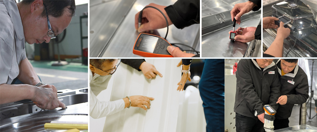
The tooling material should be selected according to the expected molding temperature, pressure, production volume, dimensional requirements, surface quality, and tool life.
Different composite applications may require different tooling materials or construction methods. For production tooling, material selection should balance dimensional stability, wear resistance, machinability, thermal behavior, and expected service life.
The correct choice is therefore not simply the material with the highest hardness or strength. It should be the material and construction approach that provides the required performance under the actual molding conditions.
Manufacturing a precision composite mold requires coordinated engineering and machining operations. A typical tooling workflow may include:
| Problem | Possible Cause | Engineering Consideration |
|---|---|---|
| Dimensional Variation | Thermal expansion, mould deformation, material shrinkage, or machining deviation | Improve tooling rigidity, dimensional compensation, and process control |
| Excessive Flash | Parting-line clearance, mould wear, material loading, or molding pressure | Improve parting surfaces and review process conditions |
| Surface Defects | Poor cavity finish, contamination, trapped air, or unstable processing | Improve surface finishing, cleaning, venting, and process stability |
| Warping | Uneven curing, thermal imbalance, or residual stress | Improve thermal distribution and review product and mould design |
| Difficult Demoulding | Insufficient draft, surface adhesion, or unsuitable cavity geometry | Review draft angles, surface condition, and release strategy |
| Incomplete Filling | Restricted material flow, incorrect loading, or unsuitable process parameters | Review material placement, flow paths, venting, and molding conditions |
A composite molding defect should not automatically be considered a tooling problem. Material properties, equipment, temperature, pressure, curing conditions, charge placement, and other process parameters can also influence the final result.
Composite molds are used across many industries because reinforced composite materials can provide a useful combination of strength, weight efficiency, corrosion resistance, and design flexibility.
The tooling configuration should always be adapted to the specific application rather than treating composite molds as a standardized product category.
Choosing a composite mold manufacturer should involve more than comparing mould prices. The supplier should understand the relationship between composite material behavior, product geometry, tooling structure, molding equipment, and production conditions.
Important evaluation criteria include:
A reliable tooling partner should be able to explain not only how the mould will be manufactured, but also how the tooling design supports the intended production process.
Customers can provide the following information to help the tooling engineer evaluate a composite mold project:
Complete product and process information allows the mould structure to be developed around actual manufacturing conditions and can reduce unnecessary tooling changes later in the project.
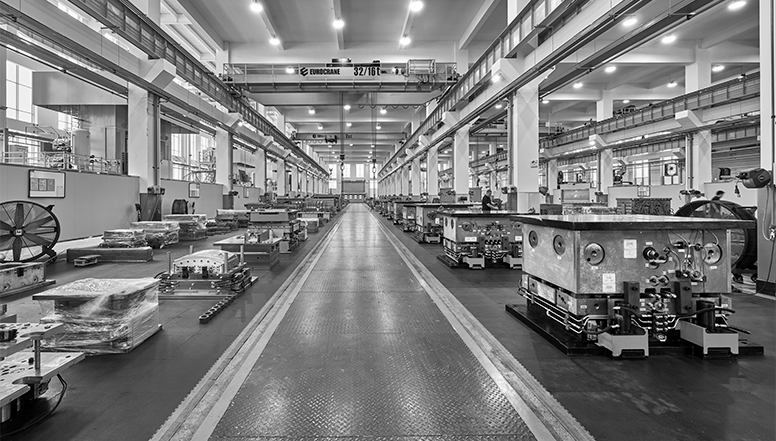
MDC manufactures customized composite molds and composite tooling for different composite manufacturing applications. Our engineering approach combines mould design, precision machining, surface finishing, assembly, inspection, and tooling validation.
Rather than applying the same mould structure to every project, MDC considers the product geometry, composite material, molding process, production volume, equipment, and required product quality when developing the tooling.
Product geometry and manufacturing requirements are reviewed before mould construction begins. This helps identify potential issues related to draft, parting lines, material flow, demoulding, and tooling structure.
CNC machining and precision finishing are used to produce cavity and core surfaces according to the approved tooling design.
MDC's tooling experience covers applications involving SMC, BMC, carbon fiber, FRP, and other composite materials and forming processes.
The final objective is not simply to manufacture an accurate mould. The tooling should support stable production, consistent part quality, efficient demoulding, and practical maintenance throughout its service life.
A composite mold is a precision tooling system used to form or cure composite materials into a specific product geometry. It can be designed for materials and processes including carbon fiber, SMC, BMC, FRP, prepreg, compression molding, and other composite manufacturing methods.
The terms are often used interchangeably in composite manufacturing. In general, composite tooling can refer to the broader tooling system used for composite production, while a composite mold specifically refers to the forming tool or mould surface that defines the component geometry.
The suitable material depends on the tooling design and manufacturing process. Composite molds may be designed for carbon fiber composites, SMC, BMC, FRP, prepreg, and other reinforced polymer systems.
The mould cavity can directly influence the surface appearance of the finished composite part. Accurate machining and appropriate polishing help reproduce the required surface characteristics consistently.
Temperature can influence material flow, curing, dimensional stability, and cycle consistency. A suitable heating configuration helps establish more stable thermal conditions throughout the mould.
It depends on the material systems and molding processes involved. Tooling temperature, pressure, chemical compatibility, surface requirements, and curing conditions should be evaluated before using a mould for a different material.
Yes. MDC manufactures customized composite molds according to product geometry, material, molding process, production volume, equipment, surface requirements, and customer specifications.
Yes. MDC manufactures customized tooling for carbon fiber and other composite applications, with mould design adapted to the selected material and production process.
Yes. MDC manufactures customized SMC and BMC compression moulds for automotive, electrical, sanitaryware, industrial, and other composite applications.
A high-performance composite mold is more than a precisely machined cavity. It is an engineered tooling system in which dimensional accuracy, mould rigidity, surface finish, thermal stability, venting, parting-line control, and demoulding performance work together.
Because composite materials and molding processes vary significantly, the tooling should be developed according to the actual application rather than using a universal mould structure.
At MDC, we manufacture composite molds, composite moulds, compression moulds, carbon fiber tooling, SMC moulds, BMC moulds, and customized composite tooling for a wide range of industrial applications.
From product analysis and DFM to mould design, CNC machining, surface finishing, assembly, inspection, and trial molding, MDC focuses on producing tooling that supports reliable and repeatable composite manufacturing.
Contact MDC for a customized composite mold solution based on your product, material, molding process, and production requirements.
Contact US
Email: master@zjmdc.com
Tel: +86 576 84616076
Fax: +86 576 84616079
Mobile: +86 13906573507(Mr. Wang)
Address: No.116 mochuang road, Huangyan Xinqian street,Taizhou,Zhejiang,China