
Specialize in Compression molds
Specialize in Compression molds
Precision mold manufacturing involves more than machining the main cavity and core surfaces. Depending on the mold design, additional holes and interfaces may be required for mounting, alignment, fastening, locating, lifting or the installation of auxiliary components. Drilling fixtures support these operations by helping establish repeatable workpiece positioning, stable clamping and controlled tool guidance where required. For manufacturers of SMC, BMC, GMT, LFT and carbon fiber molds, these auxiliary tooling methods can contribute to machining consistency when they are selected for the specific operation.
At MDC Mould, drilling should be understood within the wider context of mold manufacturing and machining operations. The fixture is a supporting tool used for a particular task; it is not the primary product or the defining business of a mold manufacturer.
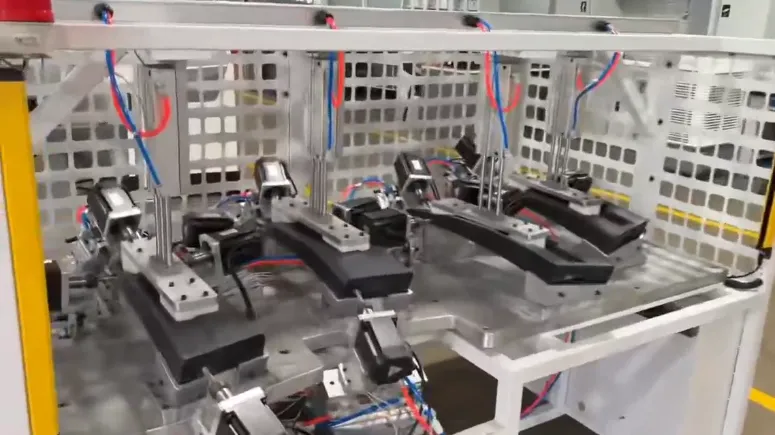
A mold contains multiple features that must work together as an integrated tool. Depending on its design, these may include mounting holes, alignment features, threaded interfaces, insert locations, ejector-related components and other machined details. Errors in the position or orientation of these features can complicate assembly, affect component alignment or create additional fitting work.
The consequences depend on the function of each hole. A mounting hole that does not align with the machine interface may delay installation. A hole associated with an insert or mating component may affect assembly fit. A misplaced feature can also introduce rework if it is discovered only after subsequent machining or mold assembly.
A drilling fixture can help reduce variation in suitable operations by defining how a component is positioned and held. However, fixture use alone does not guarantee accuracy. The result also depends on the machining equipment, cutting tool, workpiece condition, fixture quality and inspection method.
Drilling fixtures are not required for every mold component or every hole. Many features can be machined directly on suitable CNC equipment using the machine coordinate system, workpiece probing, dedicated setups or other established methods. A separate fixture becomes relevant when the geometry, production sequence, repeated loading requirements or machining arrangement makes additional workholding or guidance useful.
| Machining Situation | Potential Challenge | Possible Supporting Method |
|---|---|---|
| Repeated drilling on similar components | Variation caused by manual positioning or inconsistent setup | Dedicated locating features or a suitable repeatable workholding arrangement |
| Holes referenced to specific component datums | Incorrect relationship between the hole pattern and functional surfaces | Datum-based positioning and appropriate inspection |
| Drilling in a restricted working area | Limited tool access or difficult workpiece support | A setup designed around tool clearance, support and the machining sequence |
| Operations requiring additional drill guidance | Unwanted tool deviation under the applicable machining conditions | Drill guide sleeves where technically appropriate |
| Machining a component that can move under cutting loads | Shifting, vibration or inconsistent seating | Improved support, suitable clamping and a review of cutting conditions |
| Machining features for later assembly | Hole positions do not match mating components | Common datum references and dimensional verification |
The selection should be based on the actual machining problem. Adding a fixture where a well-controlled CNC setup is sufficient may increase setup complexity without providing a meaningful benefit. Conversely, an unsuitable manual setup can create unnecessary variation when a repeatable locating arrangement would be more appropriate.
Locating pins establish reference points that help position a component in a repeatable manner. In a drilling setup, their effectiveness depends on the relationship between the locating arrangement, the workpiece datum scheme and the required hole coordinates.
The locating strategy should be derived from the component drawing and the function of the features being machined. A suitable datum scheme identifies the surfaces or features used to establish the workpiece position. Locating pins should then be arranged to maintain the intended relationship between those references and the hole pattern.
Selecting reference points solely because they are easy to access can create dimensional errors. The workpiece may be positioned consistently against the chosen references, yet the resulting holes may not align with the intended assembly datums.
A locating arrangement must accommodate the actual geometry and expected variation of the component. An overly restrictive arrangement can make loading difficult or prevent the workpiece from seating consistently. An arrangement with insufficient constraint may allow unwanted movement.
The appropriate solution depends on component geometry, manufacturing tolerances, the number of locating features and the way the part is loaded and removed.
Repeated contact may wear locating features or change their fit. Where positioning is critical, the manufacturing and maintenance plan should identify which features require inspection and how wear will be evaluated.
Pin material, fit, hardness and surface treatment should be selected according to the application. These parameters should be defined by engineering requirements rather than assumed to be identical for every drilling setup.
Drill guide sleeves provide a guiding surface for a cutting tool in applications where additional guidance is required. They may help control tool entry relative to the workpiece, but they are not a universal requirement for drilling operations.
A guide sleeve can only support the intended hole location if its position is correctly established relative to the workpiece references. If the sleeve itself is misplaced, it may guide the drill consistently toward an incorrect location.
Critical guide locations should therefore be checked against the approved drawing or fixture specification. Where several holes must maintain a defined relationship, the inspection method should evaluate the relevant hole pattern rather than relying only on individual visual checks.
The clearance between the drill and sleeve must be suitable for the tool and machining conditions. Excessive clearance may reduce the intended guiding effect, while insufficient clearance can cause interference or unwanted friction.
The design should also consider chip evacuation, drilling depth, tool approach and access for cleaning or replacement. Where wear is expected, replaceability may be a useful maintenance consideration.
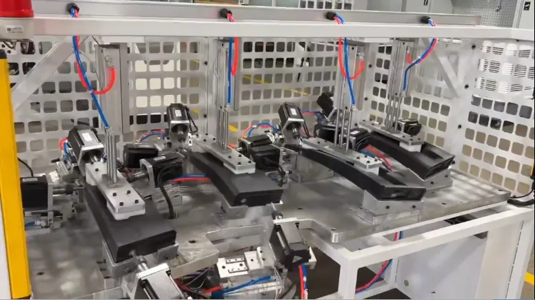
Correct positioning before machining does not guarantee that a component will remain in position under cutting loads. Inadequate support, unsuitable clamp direction or excessive local clamping force may contribute to movement, vibration or deformation.
Workpiece support should be considered in relation to the cutting forces and the component's structural stiffness. Thin or irregular components may require particular attention because unsupported areas can deflect under clamping or machining loads.
The clamping mechanism should maintain contact between the workpiece and its intended locating surfaces. The force direction, contact area and support locations should be evaluated together to avoid lifting, rotation or unacceptable deformation.
A fixture must provide sufficient clearance for the cutting tool, operator and chip removal. It should also allow the relevant features to be inspected. A stable arrangement that obstructs the machining path or makes cleaning impractical may introduce other production problems.
Fixture rigidity is therefore only one part of the solution. Stable workholding requires the correct combination of support geometry, clamping, machine setup and operating conditions.
If a machined hole fails to meet the drawing requirements, the investigation should consider the entire machining system. The fixture may contribute to the problem, but the cause may also lie in the machine, cutting tool, workpiece variation or setup procedure.
| Observed Problem | Possible Contributing Factors | Recommended Check |
|---|---|---|
| Hole position varies between setups | Inconsistent locating, incorrect datum references or setup variation | Verify datum selection, locating features and workpiece seating |
| Hole position is consistently offset | Incorrect coordinates, misplaced guide features or machine setup error | Compare the machining program, fixture references and measured coordinates |
| Hole axis does not meet orientation requirements | Workpiece alignment, tool deflection, machine alignment or unsuitable guidance | Check the setup, tool condition, guiding arrangement and inspection results |
| Workpiece moves during drilling | Insufficient clamping, inadequate support or excessive cutting loads | Review support locations, clamping and cutting conditions |
| Hole quality changes during repeated production | Tool wear, locating wear, machine variation or changing process conditions | Compare tool condition, fixture inspection records and machining results |
| Assembly holes do not align with mating components | Datum mismatch, dimensional variation or incorrect feature coordinates | Verify both component references and the applicable assembly requirements |
| Loading or unloading is inconsistent | Restricted access, unclear orientation or an unsuitable locating arrangement | Review the loading sequence, operator access and component seating |
These checks are intended to guide diagnosis, not to identify a root cause without evidence. Corrective action should follow dimensional inspection, setup review and, where necessary, a controlled machining trial.
A hole that appears acceptable on its own may still fail to meet its functional purpose if it does not align with a mating component or the specified datum system. Verification should therefore be based on the engineering drawing and the role of each feature in the complete mold.
| Feature to Verify | Why It Matters | Verification Basis |
|---|---|---|
| Hole coordinates | Maintain the intended relationship between features | Drawing dimensions and datum references |
| Hole diameter | Support the required fastener, insert or mating fit | Specified diameter and tolerance |
| Hole orientation | Maintain the required relationship to reference surfaces | Drawing-defined angular or perpendicularity requirements |
| Thread or fastening features | Ensure compatibility with the intended connection | Thread specification and applicable inspection method |
| Alignment with mating components | Reduce assembly mismatch and corrective fitting | Approved assembly references and dimensional checks |
| Locating and guiding components | Maintain repeatable positioning during continued use | Fixture specification and condition checks |
The appropriate inspection equipment and acceptance limits depend on the component size, required tolerance and feature geometry. No single measurement method or universal accuracy value is suitable for every mold component.
The value of a drilling fixture should be evaluated in relation to the complete manufacturing workflow. In some cases, a fixture can reduce repeated setup effort or improve positioning consistency. In other cases, direct CNC machining, probing or a different workholding strategy may be more appropriate.
A practical evaluation considers:
For complex mold components, the machining plan should also consider how drilling relates to milling, deep drilling, finishing and assembly. The sequence must be appropriate for the geometry and the drawing requirements; a fixture should not be treated as a substitute for an integrated manufacturing plan.
MDC Mould specializes in the design and manufacture of compression molds and composite tooling. Its work covers applications involving materials such as SMC, BMC, GMT, LFT and carbon fiber composites, serving industries including automotive, electrical, transportation and sanitaryware.
Within this business, drilling and other machining operations support the production of mold components and the features required for assembly and use. MDC's published equipment information includes CNC milling and drilling and deep-drilling machines, alongside other mold manufacturing equipment.
The relevance of a drilling fixture depends on the individual machining operation. The objective is to select a suitable process and workholding method for the part geometry, required tolerances and production sequence—not to add a separate fixture where it provides no clear technical benefit.
Learn more about MDC's core capabilities:
These pages provide further information about the company's primary manufacturing business and equipment background.
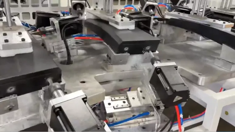
Drilling fixtures are auxiliary workholding and positioning tools used in suitable machining operations. They help establish repeatable workpiece positioning, maintain stable clamping and, where required, guide the drill. They support mold manufacturing rather than replace the mold's primary forming function.
Locating pins establish repeatable references for a workpiece. When their positions, fits and contact conditions are appropriate for the datum scheme, they can reduce variation caused by inconsistent loading and positioning.
Drill guide sleeves may be used when an operation requires additional guidance for tool entry or hole alignment. Their suitability depends on the hole requirements, workpiece geometry, tool arrangement and machining method.
No. A fixture can improve positioning repeatability, but the final result also depends on machine accuracy, tool condition, workpiece variation, fixture manufacturing quality, cutting conditions and inspection. Critical hole positions must be verified against the applicable drawing.
Verification should follow the approved engineering drawings and inspection plan. Depending on the feature, checks may include hole position, diameter, orientation, thread requirements, alignment with mating components and the condition of relevant locating or guiding features.
No. Some components can be machined effectively using suitable CNC setups, probing or other workholding methods. A dedicated fixture should be considered when it addresses a specific positioning, access, repeatability or production requirement.
Important factors include the component geometry, datum scheme, hole tolerances, machine capability, tool access, expected production frequency, clamping stability and inspection requirements. The selected method should suit the actual operation.
Drilling fixtures can support precision mold manufacturing by improving workpiece positioning, clamping stability and tool guidance in suitable operations. Their effectiveness depends on correct datum selection, appropriate fixture geometry, compatible machining conditions and verification against the engineering drawing.
For mold manufacturers, these auxiliary tooling decisions form part of a broader production system that includes mold design, CNC machining, component inspection and assembly. The aim is consistent, verifiable manufacturing quality—not the use of a dedicated fixture for its own sake.
To learn more about MDC Mould's composite and compression mold manufacturing capabilities, visit zjmdc.com or contact the team at master@zjmdc.com.
Contact US
Email: master@zjmdc.com
Tel: +86 576 84616076
Fax: +86 576 84616079
Mobile: +86 13906573507(Mr. Wang)
Address: No.116 mochuang road, Huangyan Xinqian street,Taizhou,Zhejiang,China