
Specialize in Compression molds
Specialize in Compression molds
Glass fiber is one of the most widely used reinforcement systems in composite manufacturing. But choosing glass fiber is not simply a matter of selecting a higher-strength material. Fiber type, fiber architecture, orientation, length, surface treatment and compatibility with the resin system can all influence how a composite part behaves during forming and how the tooling should be designed.
For manufacturers developing composite components, the practical question is therefore broader than “Which glass fiber is strongest?” A more useful question is: “Which reinforcement form works with the material system, manufacturing process and tooling concept?”
This relationship is particularly important for industrial composite tooling, compression molding, SMC/BMC production and other processes where material behavior directly interacts with mold geometry.
In a fiber-reinforced composite, the resin provides the matrix that binds the reinforcement and transfers loads, while the glass fibers contribute a large proportion of the structural reinforcement. The final performance therefore depends on the interaction between fiber architecture, resin chemistry, fiber volume fraction, orientation and manufacturing conditions.
Two components made with the same resin can behave very differently if their reinforcement structures are different. Likewise, the same glass fiber product may perform differently when processed through hand lay-up, vacuum infusion, RTM, pultrusion, filament winding or compression molding.
This is why material selection and tooling development should not be considered completely independent activities. The reinforcement determines how material moves, compacts and conforms to the mold, while the mold geometry determines how effectively the selected reinforcement can be converted into the required part.
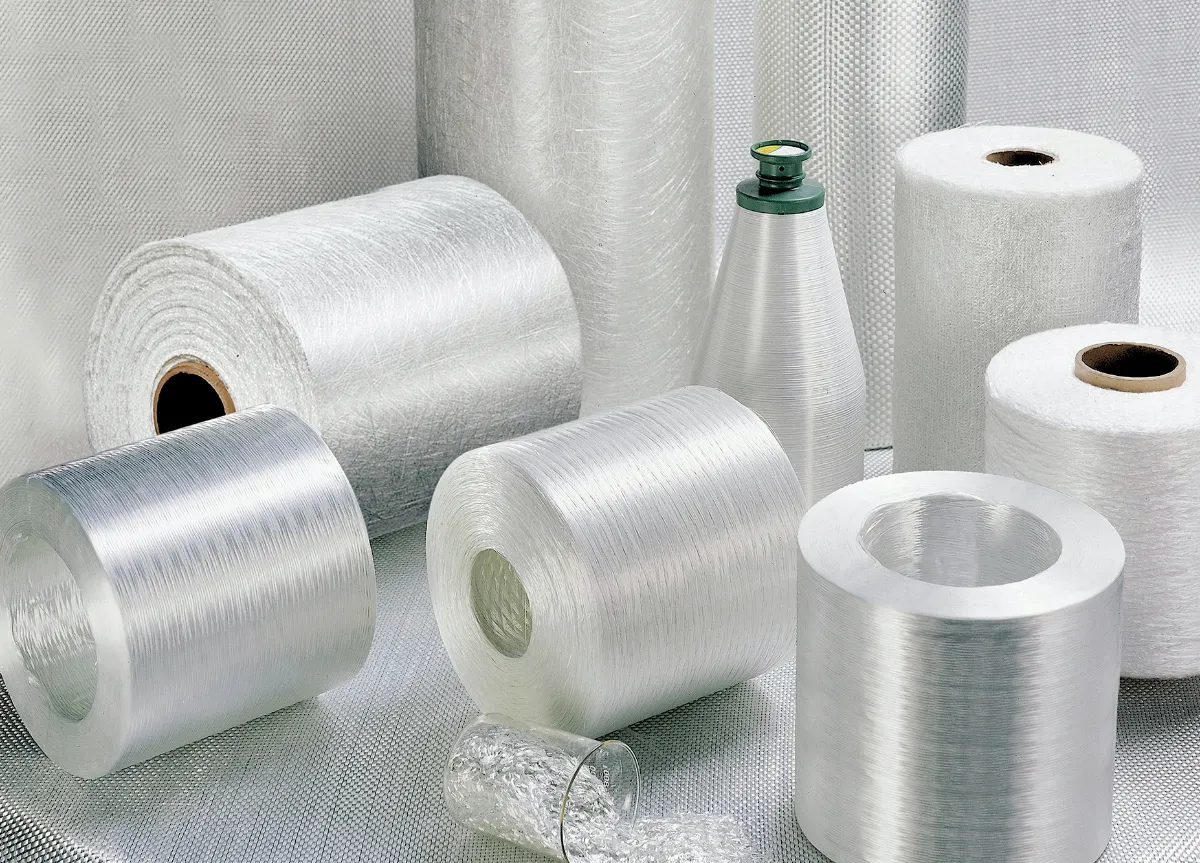
Glass fiber products are available in different material families, each developed for particular performance or environmental requirements. The appropriate choice depends on the application rather than on a simple universal ranking.
E-glass is widely used in industrial fiberglass and glass fiber reinforced composite applications. Its combination of mechanical performance, electrical properties, process compatibility and commercial availability makes it a common reinforcement for general-purpose composite manufacturing.
E-glass can be supplied in several forms, including rovings, woven fabrics, chopped strands, mats and stitched fabrics. The reinforcement form often has as much practical influence on processing as the underlying glass type.
C-glass is associated with applications where chemical resistance is an important consideration. It may be used in corrosion-oriented composite structures and protective layers where environmental exposure is a primary concern.
Selection should still be based on the complete resin-fiber system and the actual service environment rather than considering the fiber independently.
Alkali-resistant glass fiber is primarily associated with cementitious and construction-related composite systems. Its chemical resistance makes it suitable for environments where conventional glass reinforcement may not provide the required durability.
High-performance glass fibers can provide higher mechanical properties than conventional reinforcement systems, making them suitable for selected demanding structural applications.
However, higher material performance does not automatically mean better manufacturing economics. Fiber cost, availability, processing requirements and the actual structural target should all be considered during material selection.
For composite manufacturers, “glass fiber” describes a broad material family rather than a single product. The reinforcement may arrive as continuous roving, woven fabric, chopped strand mat, stitched multiaxial fabric, chopped strands or a pre-engineered molding compound.
These forms behave differently during forming. As a result, the reinforcement architecture can influence both part performance and tooling requirements.
| Glass Fiber Form | Typical Manufacturing Route | Primary Characteristic | Tooling Relevance |
|---|---|---|---|
| Continuous Roving | Pultrusion, filament winding, spray-up | Continuous reinforcement and high production efficiency | Requires controlled fiber guidance or material placement |
| Woven Fabric | Hand lay-up, RTM, selected closed-mold processes | Defined fiber directions and good handling | Surface geometry and drape affect conformity |
| Chopped Strand Mat | Hand lay-up and selected molding processes | Relatively isotropic reinforcement behavior | Useful for complex contours and transition regions |
| Stitched Multiaxial Fabric | Vacuum infusion, RTM and structural composite processes | Multiple engineered fiber orientations | Tool geometry must accommodate thickness and local draping |
| Chopped Glass Fiber | SMC, BMC and thermoset molding compounds | Suitable for high-volume molding | Material flow and cavity filling become critical |
| Glass Fiber Powder / Milled Fiber | Filled compounds and modification systems | Property modification rather than primary structural reinforcement | Influences shrinkage, stiffness and surface behavior |
Woven fabric contains interlaced yarns arranged in defined directions. Plain, twill and satin constructions provide different combinations of stability, drapability and surface characteristics.
Woven reinforcement can be useful when the designer needs controlled fiber directions. However, the woven architecture also introduces crimp because the yarns pass over and under one another. This is one reason why reinforcement architecture should be considered when optimizing structural efficiency.
Chopped strand mat contains randomly distributed short glass fibers held together by a binder. The relatively non-directional fiber arrangement can be useful for complex shapes and transition regions.
It can also help create a more uniform surface and provide a practical intermediate layer between different reinforcement structures. However, it should not automatically be treated as a substitute for engineered directional reinforcement in highly loaded structures.
Multiaxial fabrics combine reinforcement layers oriented in different directions and hold them together through stitching. This allows designers to build a laminate around specific load paths more efficiently than relying only on conventional woven fabric.
For large structural composite parts, however, the thickness and draping behavior of the reinforcement need to be evaluated together with the mold geometry.
SMC represents a particularly important case because the glass fiber reinforcement is incorporated into a molding compound before it reaches the production mold.
Instead of manually arranging individual layers of fabric, the manufacturer works with a prepared sheet containing resin, chopped glass fibers, fillers and additives. During compression molding, the charge is placed into the mold and compressed while the material flows toward the required geometry.
This changes the tooling problem. The mold is no longer responsible only for reproducing the final surface. Its geometry also influences how the molding compound fills ribs, corners, openings, bosses and other features.
Chopped glass fibers can provide an effective balance between reinforcement and moldability. But fiber movement during compression can also influence local orientation and therefore local mechanical behavior.
Tool designers should therefore consider the relationship between charge placement, flow distance, cavity geometry and the location of critical structural features.
A relatively simple panel may have a predictable filling pattern. A component containing deep ribs, bosses, apertures and varying wall thicknesses can be much more difficult.
In these cases, mold development should consider not only whether the cavity can be filled, but also whether the material can reach the required areas without producing unacceptable fiber movement, local accumulation or incomplete filling.
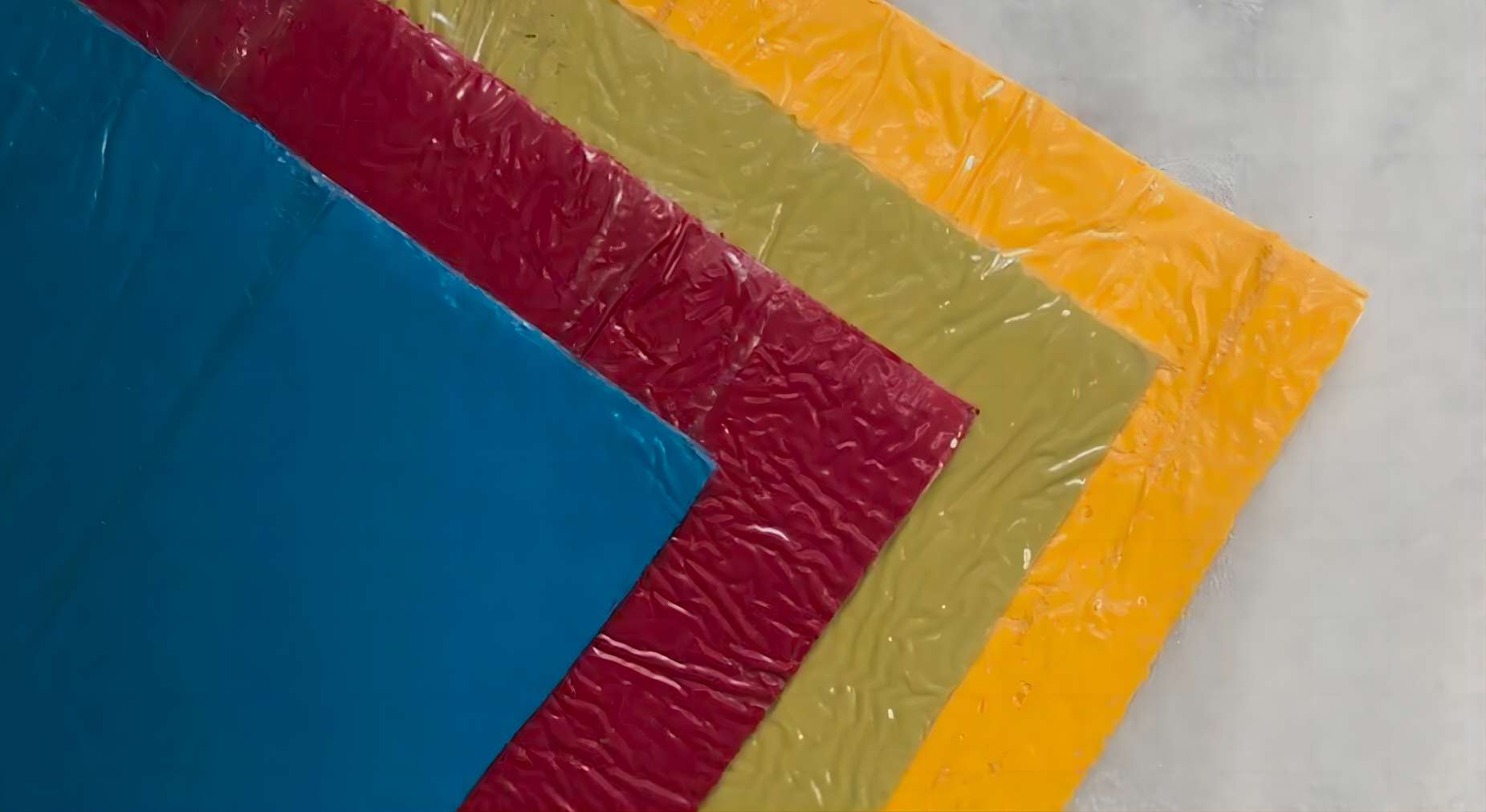
The reinforcement system can affect several fundamental tooling decisions. These effects are especially important when the same basic part geometry may be manufactured using different composite processes.
The mold surface must provide the required final geometry while allowing the selected reinforcement to conform to the cavity. Sharp transitions can be difficult for certain reinforcement architectures, particularly when the material has limited drapability.
A larger and properly controlled radius can improve fiber conformity and reduce the risk of bridging. The appropriate radius depends on the material architecture, laminate design and structural requirements.
Reinforced composite parts often contain complex profiles. The parting line must provide a practical release path while minimizing unwanted flash and protecting critical interfaces.
Air and volatile materials must be able to escape from appropriate areas of the mold. Poor venting can contribute to voids, surface defects or incomplete consolidation depending on the process.
Reinforcement architecture does not eliminate the need for practical release geometry. Deep ribs, narrow cavities and complex profiles can increase demoulding forces and require careful draft and tooling strategy.
Fiber-reinforced composites are not automatically isotropic materials. Their mechanical behavior can depend strongly on fiber orientation.
Continuous reinforcement aligned with a major load direction can provide efficient load carrying. Randomly distributed chopped fibers produce a different mechanical response. Multiaxial reinforcement provides yet another approach by distributing reinforcement across several directions.
For tooling engineers, this means that the final mold geometry should be evaluated together with the intended reinforcement architecture. A mold that is geometrically correct may still create manufacturing difficulties if its features force the material into unfavorable fiber configurations.
| Common Mistake | Potential Consequence | Better Engineering Approach |
|---|---|---|
| Selecting fiber only by nominal strength | Material may be difficult to process or unnecessarily expensive | Evaluate strength, architecture, process and cost together |
| Using directional reinforcement for every region | Complex contours may become difficult to form | Combine reinforcement architectures according to structural and forming needs |
| Ignoring fiber movement during compression molding | Local fiber orientation and thickness may vary | Consider charge placement and cavity flow during tooling development |
| Designing sharp corners for complex fabrics | Bridging, wrinkling or incomplete conformity | Use suitable radii and validate material draping |
| Choosing reinforcement before defining the manufacturing process | Material and process may become incompatible | Develop material and process selection together |
| Assuming the same mold works equally well for every reinforcement | Flow, filling and release behavior can change | Review tooling against the actual material system |
There is no single glass fiber product that is optimal for every composite manufacturing process. A practical selection begins with the production method.
Woven fabrics and chopped strand mats are commonly considered for hand lay-up because they can be positioned manually and adapted to different contours. Tool surface quality and release characteristics are especially important when the finished component requires a good surface appearance.
Continuous and stitched reinforcement systems can be used in vacuum-assisted processes where resin must flow through the reinforcement architecture. Permeability, laminate thickness and flow path become important factors.
RTM requires a reinforcement preform that can be positioned inside a closed mold while allowing resin to impregnate the structure. Mold sealing, injection strategy, venting and reinforcement permeability therefore become closely connected.
Continuous glass fiber rovings are particularly relevant to pultrusion because the reinforcement is continuously pulled through a shaped die. The tooling concept is fundamentally different from a conventional compression mold because production depends on continuous material guidance and consolidation.
Roving is wound around a mandrel according to a defined fiber angle. The reinforcement architecture is therefore established through the winding path rather than a conventional mold cavity.
Compression molding requires particular attention to material charge, cavity filling, pressure distribution and temperature. When SMC or BMC is used, chopped reinforcement is already incorporated into the molding compound.
For this reason, compression mold design should take material flow and structural features into account from the beginning.
A reliable composite manufacturing project usually benefits from evaluating material and tooling together. A practical workflow can include the following stages.
Identify the required stiffness, strength, impact resistance, dimensional stability, environmental resistance and production volume.
Determine whether the component requires woven fabric, mat, multiaxial reinforcement, continuous roving, chopped fiber or a molding compound.
Match the reinforcement and resin system with hand lay-up, infusion, RTM, pultrusion, winding, compression molding or another suitable process.
Identify deep sections, ribs, bosses, corners, openings, flange areas and other features that may influence material placement or flow.
Establish cavity geometry, parting lines, draft, venting, support structure and release strategy based on the actual material and process.
Precision machining and dimensional inspection help ensure that the working surfaces reproduce the intended component geometry.
Trial production should be used to examine filling, material behavior, release, surface quality, dimensional consistency and other process-specific characteristics.
One of the most common mistakes in composite development is treating material selection as a finished decision before tooling engineering begins.
In reality, the two stages can influence each other. If the selected reinforcement cannot conform to a required feature, the geometry may need modification. If the geometry cannot be changed, a different reinforcement architecture or forming strategy may be required.
The same principle applies to production volume. A reinforcement system that works well for prototype production may not be the most practical solution for high-volume compression molding.
Therefore, an effective composite tooling strategy should consider material, geometry and production method as a connected engineering system.
When requesting tooling for a glass fiber reinforced composite component, supplying only a 3D CAD model may not be enough for an accurate tooling assessment.
Useful project information may include:
The more clearly the material and process conditions are defined, the easier it is for the tooling manufacturer to evaluate mold architecture, production feasibility and potential manufacturing risks.
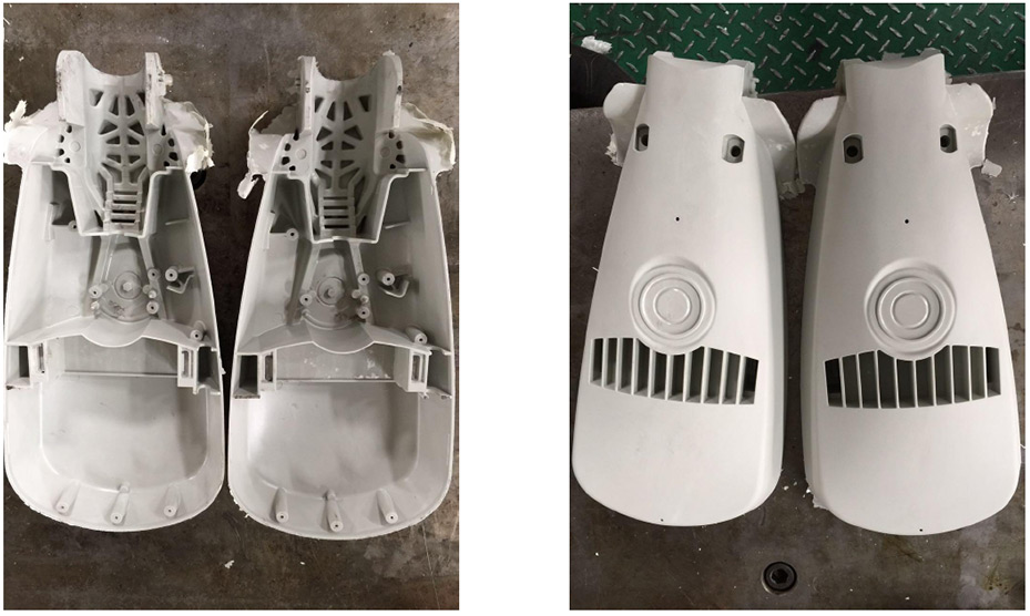
MDC provides composite mold and tooling development for applications where part geometry, material behavior and production requirements must be considered together.
For glass fiber reinforced components, the tooling approach can be influenced by reinforcement architecture, forming process, structural features and production volume. This is especially relevant for compression molding applications where material flow and cavity geometry interact directly.
MDC's tooling engineering approach focuses on the manufacturability of the complete part rather than treating the mold as an isolated CAD reproduction.
Depending on project requirements, tooling development can involve mold structure design, precision machining, parting-line development, surface finishing, dimensional inspection and mold trial support.
E-glass is widely used in general industrial glass fiber reinforced composites because of its combination of mechanical properties, electrical characteristics, process compatibility and commercial availability. The appropriate reinforcement form still depends on the manufacturing process and application.
Roving consists of continuous glass fiber strands and is commonly used in processes such as pultrusion, filament winding and selected spray-up applications. Woven fabric contains interlaced yarns arranged in defined directions and is commonly used where controlled reinforcement orientation and handling are important.
Chopped glass fiber provides reinforcement while allowing the molding compound to flow during compression molding. Its length and distribution influence both mechanical behavior and processing characteristics.
Yes. Reinforcement architecture can affect draping, flow, compaction, local thickness and release behavior. Tooling should therefore be developed according to the actual material system and manufacturing process.
Compression molding commonly uses molding compounds such as SMC and BMC, where chopped glass fiber is incorporated into the material before molding. The suitable formulation depends on the required mechanical properties, geometry and production conditions.
It may be technically possible in some cases, but compatibility should be evaluated rather than assumed. Changes in reinforcement architecture, material flow, thickness or processing temperature can affect filling, release and dimensional behavior.
Glass fiber selection should not be reduced to a comparison of nominal strength. Fiber type, reinforcement architecture, orientation, resin compatibility and manufacturing process all contribute to the performance and manufacturability of a composite component.
For tooling engineers, the most important point is that the material choice also influences the mold. Woven fabric, chopped strand mat, multiaxial reinforcement, continuous roving and SMC chopped fiber do not behave identically during forming.
Their differences can affect material placement, flow, corner conformity, compaction, venting, parting-line design and demoulding.
A successful composite project therefore connects three elements from the beginning: material architecture, manufacturing process and tooling design.
When these three elements are developed together, the mold is no longer simply a tool for reproducing geometry. It becomes part of the process system that converts glass fiber reinforcement into a repeatable, dimensionally controlled composite component.
Contact US
Email: master@zjmdc.com
Tel: +86 576 84616076
Fax: +86 576 84616079
Mobile: +86 13906573507(Mr. Wang)
Address: No.116 mochuang road, Huangyan Xinqian street,Taizhou,Zhejiang,China