
Specialize in Compression molds
Specialize in Compression molds
Electrical enclosure covers require more than dimensional accuracy. They must provide stable mechanical performance, consistent wall thickness, reliable electrical insulation, and a high-quality surface finish to ensure dependable assembly and long-term service.
Compression moulding is well suited for manufacturing SMC electrical components because it can produce complex composite geometries with consistent dimensions, excellent surface quality, and repeatable production performance. For medium- and high-volume manufacturing, a properly engineered SMC mould can help maintain stable product quality while reducing production variation.
At MDC, we manufacture customized compression moulds for electrical enclosure covers and other SMC electrical components. Our tooling solutions are developed according to product geometry, material characteristics, press conditions, production volume, and customer quality requirements.
Electrical enclosure covers are often required to combine mechanical strength, dimensional stability, electrical insulation, heat resistance, and long-term environmental durability. These requirements make fiber-reinforced thermoset composites such as SMC suitable for many electrical enclosure applications.
Compared with conventional materials, SMC can provide a combination of structural and electrical properties while supporting efficient compression moulding production. The material can also be molded into complex shapes with ribs, mounting features, bosses, openings, and other integrated details.
A well-designed SMC compression mould helps manufacturers achieve:
However, these advantages depend heavily on the quality of the mould and the control of the compression moulding process. Mould geometry, material flow, temperature distribution, venting, and demoulding all influence the final electrical enclosure cover.
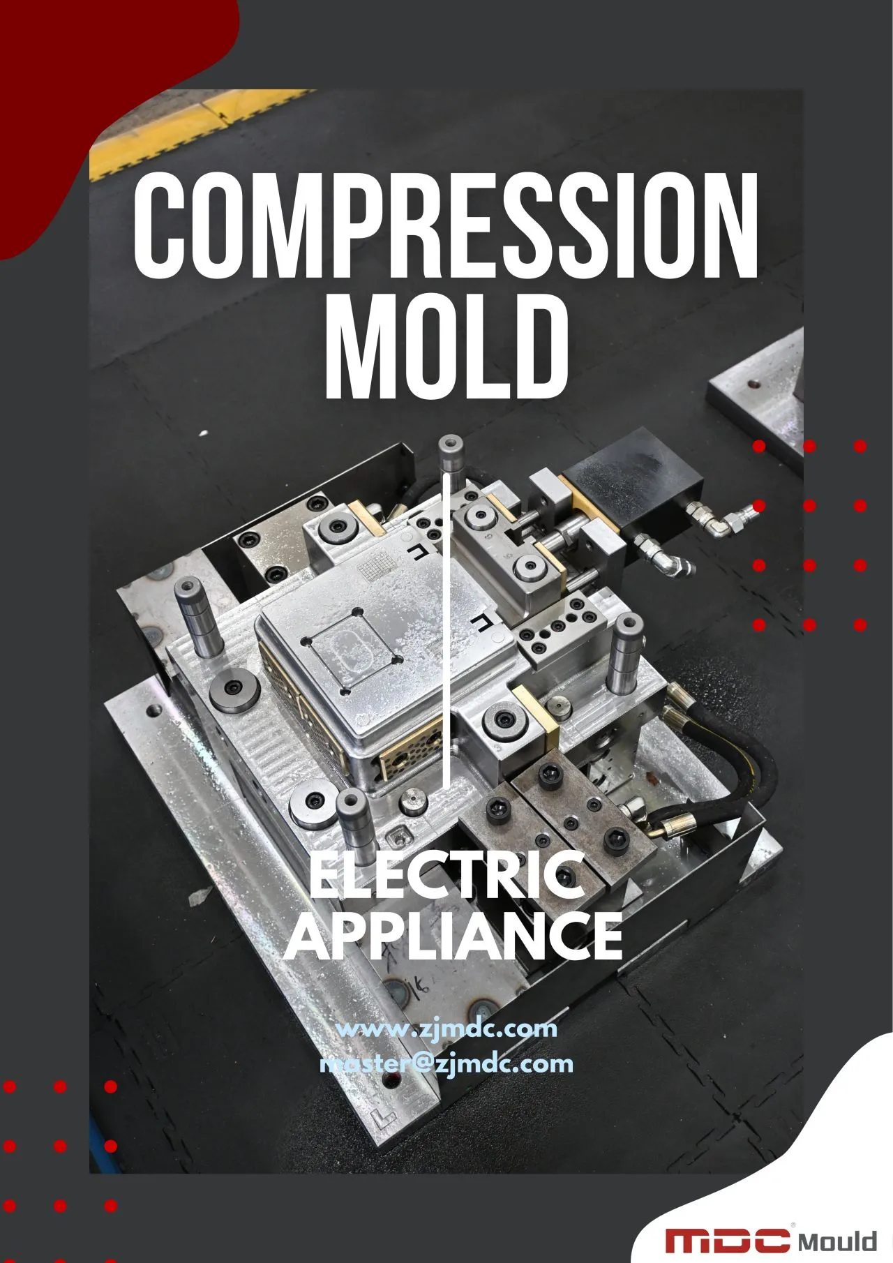
An electrical enclosure cover may appear relatively simple from the outside, but its internal structure can contain multiple functional features. Mounting holes, ribs, sealing areas, screw bosses, reinforcing sections, and interfaces with the enclosure body must all be accurately reproduced by the mould.
For this reason, the design of an electrical enclosure mould should consider both product geometry and the behavior of SMC during compression moulding.
Dimensional accuracy is critical because electrical enclosure covers must normally fit with a corresponding base, frame, gasket, fastening system, or electrical assembly. Excessive dimensional variation can create assembly difficulties or compromise sealing performance.
The mould cavity and core must therefore be manufactured according to carefully controlled engineering tolerances. Shrinkage compensation should also be considered during the tooling design stage to ensure that the finished SMC component achieves the required dimensions.
Wall thickness has a direct influence on the mechanical and dimensional performance of an electrical enclosure cover. Significant thickness variation may affect material flow, curing behavior, shrinkage, and local strength.
A properly engineered mould helps distribute SMC material consistently throughout the cavity while maintaining the intended wall structure. This is particularly important for covers containing ribs, corners, bosses, and reinforced sections.
The parting line is another important consideration when designing a compression mould for electrical covers. Its position influences flash formation, dimensional accuracy, mould maintenance, and the appearance of the finished component.
An optimized parting line should provide reliable mould closure while minimizing excessive flash and avoiding interference with important sealing or assembly surfaces.
During compression moulding, SMC material is placed into the mould and compressed under controlled pressure and temperature. As the mould closes, the material flows through the cavity before curing into the final composite structure.
The flow behavior of SMC must be considered carefully when designing an SMC mould for electrical covers. Complex geometry, long flow distances, narrow sections, ribs, and changes in wall thickness can all affect material distribution.
Poor material flow may result in:
Mould engineers therefore evaluate the product geometry and material loading strategy before finalizing the tooling design. The objective is to achieve predictable material flow and sufficient cavity filling without creating unnecessary pressure concentrations or excessive material movement.
Venting is an important part of compression mould design for electrical components. During mould closing and curing, air and gases must be released from the cavity. If they become trapped, surface defects, voids, incomplete filling, or localized quality problems may occur.
Properly positioned vents provide controlled pathways for air and gases to escape while minimizing unwanted SMC leakage.
For electrical enclosure covers, effective venting contributes to:
The venting strategy should be developed according to cavity geometry, material flow direction, parting line configuration, and expected production conditions rather than relying on a standard vent arrangement.
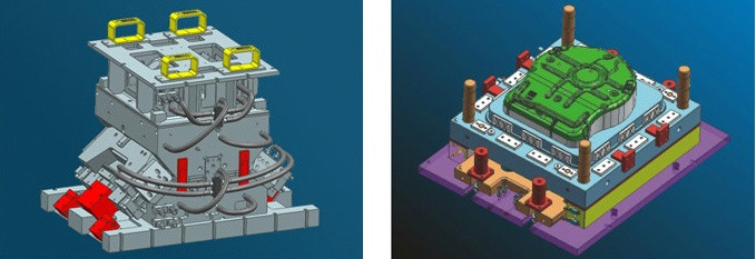
Temperature control is one of the most important factors in producing consistent SMC electrical enclosure covers. Because SMC is a thermosetting composite material, the molding temperature directly affects resin flow, curing behavior, dimensional stability, surface quality, and cycle time.
An SMC compression mould should therefore be designed with a heating system that provides stable and reasonably uniform temperature distribution across the cavity and core. Uneven heating can cause different areas of the component to cure at different rates, increasing the risk of warpage, dimensional variation, or surface defects.
Large electrical enclosure covers often have relatively broad molding surfaces. If the temperature distribution is not properly balanced, different regions of the part may experience different curing conditions.
MDC considers the mould structure, cavity geometry, heating arrangement, and expected production cycle when developing the thermal system. The objective is to provide stable heating conditions throughout the molding area and maintain repeatable production performance.
Stable mould temperature helps maintain predictable SMC flow and curing behavior. This contributes to consistent dimensions, surface appearance, and mechanical properties from one production cycle to the next.
For production environments where electrical enclosure covers are manufactured continuously, thermal stability is particularly important because small process variations can accumulate into higher rejection rates over time.
The mould surface directly influences the appearance of the finished SMC electrical cover. Electrical enclosure products may require smooth, uniform surfaces because they are often visible components or must interface with gaskets, labels, mounting hardware, and other assemblies.
A high-quality electrical enclosure mould should therefore provide a cavity surface appropriate for the customer's final product requirements.
Depending on the application, surface finishing may include:
Proper surface finishing can improve the visual consistency of molded parts while also supporting reliable demoulding. It can reduce material adhesion and make mould maintenance easier during long production runs.
Surface quality is not only an aesthetic consideration. Certain areas of an electrical cover may need to provide accurate contact with seals, fasteners, frames, or mating components. Excessive surface irregularities can therefore affect assembly performance.
For this reason, critical sealing and assembly surfaces should be identified during the mould design stage rather than treated only as a finishing issue after machining.
Reliable demoulding is essential for maintaining production efficiency. After curing, the SMC component must be removed from the mould without damaging edges, ribs, mounting features, or visible surfaces.
An improperly designed mould may create excessive demoulding resistance. This can lead to scratches, deformation, broken features, or production downtime.
Appropriate draft angles help the molded electrical cover separate from the cavity and core smoothly. The required angle depends on part geometry, surface finish, texture, material characteristics, and customer requirements.
Where the product structure requires additional assistance during demoulding, the mould design can incorporate suitable ejection or release features. These features must be positioned carefully to avoid damaging functional or cosmetic areas of the component.
Good demoulding design helps reduce:
Electrical enclosure covers are often produced in repeated molding cycles, which means the tooling must maintain its geometry under continuous mechanical and thermal loading.
A rigid compression mould minimizes deformation during press operation and helps maintain consistent cavity dimensions over long production periods. This is particularly important for larger enclosure covers where mould size and forming area increase the potential for deflection.
Mould structure should therefore be designed according to:
Adequate structural rigidity supports dimensional repeatability and helps reduce tooling deformation during production.
Tool steel selection affects machining performance, wear resistance, thermal stability, surface finishing, and mould service life. The appropriate material should be selected according to production requirements rather than using the same specification for every application.
| Mould Material | Typical Characteristics | Potential Application |
|---|---|---|
| P20 Steel | Good machinability and cost efficiency | Prototype and moderate-volume tooling |
| 718 Steel | Good strength, machinability, and polishing performance | General industrial and electrical composite tooling |
| H13 Steel | Good thermal fatigue resistance and durability | High-cycle compression moulding applications |
The final material specification should also consider heat treatment, mould operating temperature, production cycle, expected tool life, and maintenance requirements.
| Mould Design Factor | Potential Effect on Electrical Cover |
|---|---|
| Cavity Accuracy | Controls dimensional consistency and assembly fit |
| Wall Thickness Design | Influences material flow, strength, and shrinkage |
| Parting Line | Affects flash, appearance, and sealing areas |
| Venting | Helps reduce trapped air and surface defects |
| Heating System | Influences curing consistency and dimensional stability |
| Surface Finish | Affects appearance and demoulding performance |
| Mould Rigidity | Supports long-term dimensional stability |
| Draft Design | Improves demoulding and reduces part damage |
The important point is that these factors do not work independently. A reliable electrical enclosure cover mould requires the cavity, thermal system, venting structure, parting line, surface finish, and mechanical structure to work together as one tooling system.
The quality of an SMC mould directly affects the consistency of the electrical enclosure covers produced from it. For this reason, tooling quality should be controlled throughout the entire manufacturing process rather than relying only on a final visual inspection.
A professional compression mould manufacturer evaluates critical dimensions, cavity geometry, parting surfaces, heating systems, venting features, surface finish, and assembly accuracy before the mould enters production.
Critical mould dimensions are checked against approved product drawings and tooling specifications. Particular attention is given to cavity dimensions, mounting features, sealing surfaces, inserts, and parting-line areas.
Accurate dimensional inspection helps ensure that the finished SMC electrical cover meets the required assembly and functional tolerances.
The cavity surface and parting line are inspected to identify machining marks, local deformation, excessive gaps, or other conditions that could influence product quality.
A precise parting surface is especially important for controlling flash. Excessive clearance between the mould halves can allow SMC material to escape during compression and create additional trimming work.
The mould heating system should be checked before production to confirm that the designed heating configuration can provide stable thermal conditions.
Temperature verification helps identify potential hot spots or cold areas that could result in inconsistent curing or dimensional variation in the electrical enclosure cover.
Trial moulding is an essential stage in the development of an electrical enclosure cover mould. It provides an opportunity to evaluate the actual interaction between the mould, SMC material, molding press, and processing parameters.
During trial production, engineers may evaluate:
The trial results can then be used to make controlled tooling or process adjustments before mass production begins.
Even when the basic mould design is correct, production defects may occur if tooling conditions, material loading, temperature, pressure, or curing parameters are not properly controlled. Understanding the relationship between the defect and its potential cause helps engineers solve problems more efficiently.
| Defect | Possible Cause | Potential Solution |
|---|---|---|
| Excessive Flash | Parting-line clearance, excessive molding pressure, or mould wear | Improve parting surface accuracy, review pressure settings, and maintain sealing surfaces |
| Incomplete Filling | Insufficient material, unsuitable loading position, low temperature, or restricted flow | Optimize material charge, loading position, temperature, and cavity design |
| Warpage | Uneven curing, temperature imbalance, non-uniform wall thickness, or residual stress | Improve thermal balance and review product and mould geometry |
| Surface Defects | Poor mould finish, trapped air, contamination, or unstable processing conditions | Improve cavity finishing, venting, cleaning, and process control |
| Dimensional Variation | Mould deformation, inconsistent temperature, or material shrinkage variation | Improve mould rigidity, thermal control, and shrinkage compensation |
| Fiber Exposure | Material flow conditions, insufficient resin coverage, or process instability | Review material loading and molding parameters and verify mould surface condition |
| Difficult Demoulding | Insufficient draft, surface adhesion, or unsuitable cavity finish | Review draft angles, surface finish, and release conditions |
The key principle is that a molding defect should not automatically be attributed to the mould alone. Product geometry, SMC material condition, molding temperature, pressure, curing time, loading strategy, and press performance can all influence the final result.
A systematic engineering approach helps distinguish tooling-related problems from process-related problems and leads to more effective corrective action.
For complex electrical enclosure covers, the first mould trial is not simply a pass-or-fail inspection. It provides valuable production data that can be used to optimize the complete tooling and molding system.
Engineers examine the molded component to determine whether SMC material has distributed evenly throughout the cavity. Areas around ribs, corners, bosses, and deep features require particular attention because changes in geometry can influence material flow.
Critical dimensions are measured after trial molding to determine whether the mould correctly compensates for expected material shrinkage and thermal effects.
Where necessary, tooling adjustments can be made before the mould is released for production.
The molded surface is inspected for gloss variation, pits, pinholes, fiber exposure, resin-rich areas, and other visible defects. These observations help determine whether additional mould finishing, venting adjustments, or process optimization is required.
The component should separate from the mould without excessive force or damage. If sticking or deformation occurs, engineers can review draft angles, cavity surface condition, release strategy, and local product geometry.
This trial-and-optimization approach helps transform a newly manufactured mould into a production-ready tooling system rather than treating mould delivery as the end of the engineering process.
At MDC, the development of an SMC compression mould follows a structured manufacturing process designed around the customer's product requirements and production conditions.
This process allows MDC to consider the mould as part of the complete manufacturing system. The goal is not simply to produce a precisely machined tool, but to deliver tooling that can support stable and repeatable production of SMC electrical enclosure covers.
SMC electrical enclosure covers are used in applications where electrical insulation, mechanical strength, dimensional stability, and environmental resistance are important. The combination of composite material performance and compression moulding efficiency makes SMC suitable for a wide range of electrical and industrial products.
SMC enclosure covers can be used for electrical distribution equipment and protective housings where reliable insulation and dimensional stability are required. Precision tooling helps maintain consistent interfaces between covers, internal components, and enclosure bases.
Switchgear and control equipment often require protective composite covers with accurate mounting features and stable electrical insulation performance. Compression moulding allows complex ribs, bosses, and functional features to be integrated into the component.
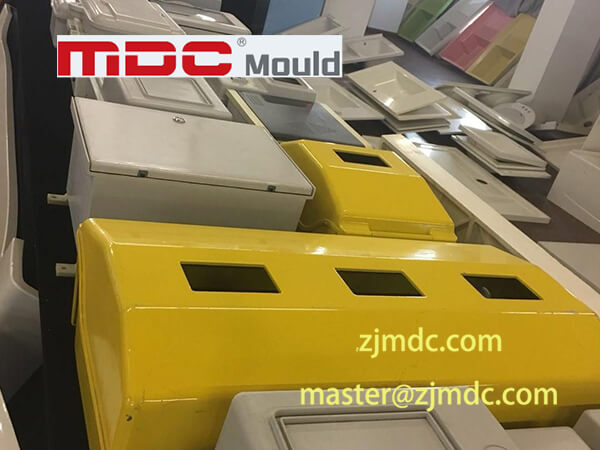
SMC is also suitable for meter boxes and electrical protection enclosures exposed to outdoor or demanding industrial environments. A properly designed mould supports consistent wall thickness and repeatable production across large quantities.
Industrial electrical systems may require custom composite covers for motors, control systems, power equipment, and other electrical assemblies. Customized SMC tooling allows manufacturers to produce components according to specific dimensions, mounting requirements, and surface specifications.
Providing complete product information at the beginning of a tooling project helps engineers develop a more accurate and production-oriented mould solution. Customers looking for an electrical enclosure cover mould should ideally provide the following information:
The more complete the initial technical information, the easier it is for the tooling engineer to optimize mould structure, material loading, heating configuration, venting, and production conditions before manufacturing begins.
Selecting a compression mould manufacturer should involve more than comparing tooling prices. The mould must perform reliably under repeated pressure and temperature cycles while maintaining the dimensional and surface requirements of the finished electrical component.
When evaluating potential tooling suppliers, manufacturers should consider:
A capable tooling supplier should be able to explain not only how the mould will be manufactured, but also how its design supports the required production process and final product quality.
MDC provides customized compression moulds for SMC electrical components, combining precision tooling manufacturing with practical knowledge of composite molding processes.
Our engineering approach considers the complete relationship between the product, material, mould, press, and molding conditions. This allows tooling decisions to be made according to actual production requirements rather than treating each mould as an isolated machining project.
MDC evaluates product geometry, wall thickness, ribs, bosses, parting lines, material flow, heating requirements, and demoulding conditions during the design stage.
Advanced CNC machining, precision finishing, grinding, fitting, and inspection processes are used to produce mould components with the required dimensional accuracy and surface quality.
MDC supports tooling validation through trial moulding and engineering evaluation. Trial results can be used to identify potential issues with filling, flash, surface appearance, dimensions, and demoulding before the tooling enters regular production.
Every electrical enclosure application has different product dimensions, material requirements, production volumes, and press conditions. MDC develops customized tooling according to the customer's specific requirements rather than relying on a one-size-fits-all mould structure.
For manufacturers developing SMC electrical enclosure covers, this integrated approach helps reduce tooling risks and supports more stable long-term production.
A compression mould for an electrical enclosure cover is a precision tooling system used to form SMC or other thermoset composite materials into the required cover geometry under controlled heat and pressure.
SMC can provide a useful combination of mechanical strength, electrical insulation, dimensional stability, and resistance to demanding service environments. It can also be compression molded into complex shapes with integrated ribs, bosses, and mounting features.
Important factors include cavity accuracy, wall thickness, material flow, parting-line design, venting, heating, surface finish, draft angles, mould rigidity, shrinkage compensation, and demoulding requirements.
Mould temperature affects SMC flow and curing behavior. Stable and appropriately distributed temperature conditions help improve dimensional consistency, surface quality, curing uniformity, and production repeatability.
Flash can result from parting-line clearance, excessive molding pressure, mould wear, incorrect material loading, or other process conditions. Improving mould accuracy and reviewing molding parameters can help reduce excessive flash.
Warpage can be influenced by uneven temperature distribution, non-uniform wall thickness, curing conditions, material shrinkage, and mould deformation. Improving thermal balance, product geometry, mould rigidity, and process control can reduce the risk.
Yes. MDC manufactures customized SMC compression moulds according to product geometry, material specifications, production volume, press conditions, surface requirements, and customer quality standards.
Yes. Trial moulding can be used to evaluate material filling, dimensions, surface quality, flash, curing, and demoulding performance and to identify potential tooling adjustments before production.
A high-quality electrical enclosure cover requires more than a correctly shaped cavity. Dimensional accuracy, wall thickness, material flow, temperature control, venting, surface finish, mould rigidity, and demoulding performance must work together to achieve stable production results.
For SMC electrical components, a professionally engineered compression mould provides the foundation for repeatable manufacturing. Proper tooling design can help reduce dimensional variation, improve surface quality, control flash, simplify demoulding, and support efficient medium- and high-volume production.
At MDC, we manufacture customized SMC moulds and compression moulds for electrical enclosure covers and other composite components. From initial DFM analysis and mould design to precision machining, trial moulding, inspection, and tooling optimization, our engineering team focuses on the complete production requirements of each project.
If you are developing an SMC electrical enclosure cover and need a reliable tooling partner, MDC can provide a customized mould solution based on your product design, material, press equipment, and production requirements.
Contact MDC for your electrical enclosure compression mould project.
Contact US
Email: master@zjmdc.com
Tel: +86 576 84616076
Fax: +86 576 84616079
Mobile: +86 13906573507(Mr. Wang)
Address: No.116 mochuang road, Huangyan Xinqian street,Taizhou,Zhejiang,China