
Specialize in Compression molds
Specialize in Compression molds
An SMC mold is more than a cavity used to shape Sheet Molding Compound. In production, the tooling directly influences material flow, curing behavior, dimensional accuracy, surface quality, flash control, demoulding, and cycle consistency.
Because SMC is processed under heat and pressure, the mould must be engineered around the interaction between material characteristics, product geometry, molding equipment, and processing conditions. Cavity geometry alone is not enough to achieve stable production.
At MDC, we manufacture customized SMC molds, SMC moulds, SMC tools, and SMC tooling for automotive, electrical, sanitaryware, industrial, transportation, and other composite applications.
Our tooling development focuses on precision machining, mould rigidity, temperature management, venting, parting-line control, surface finishing, and reliable demoulding to support repeatable SMC moulding production.
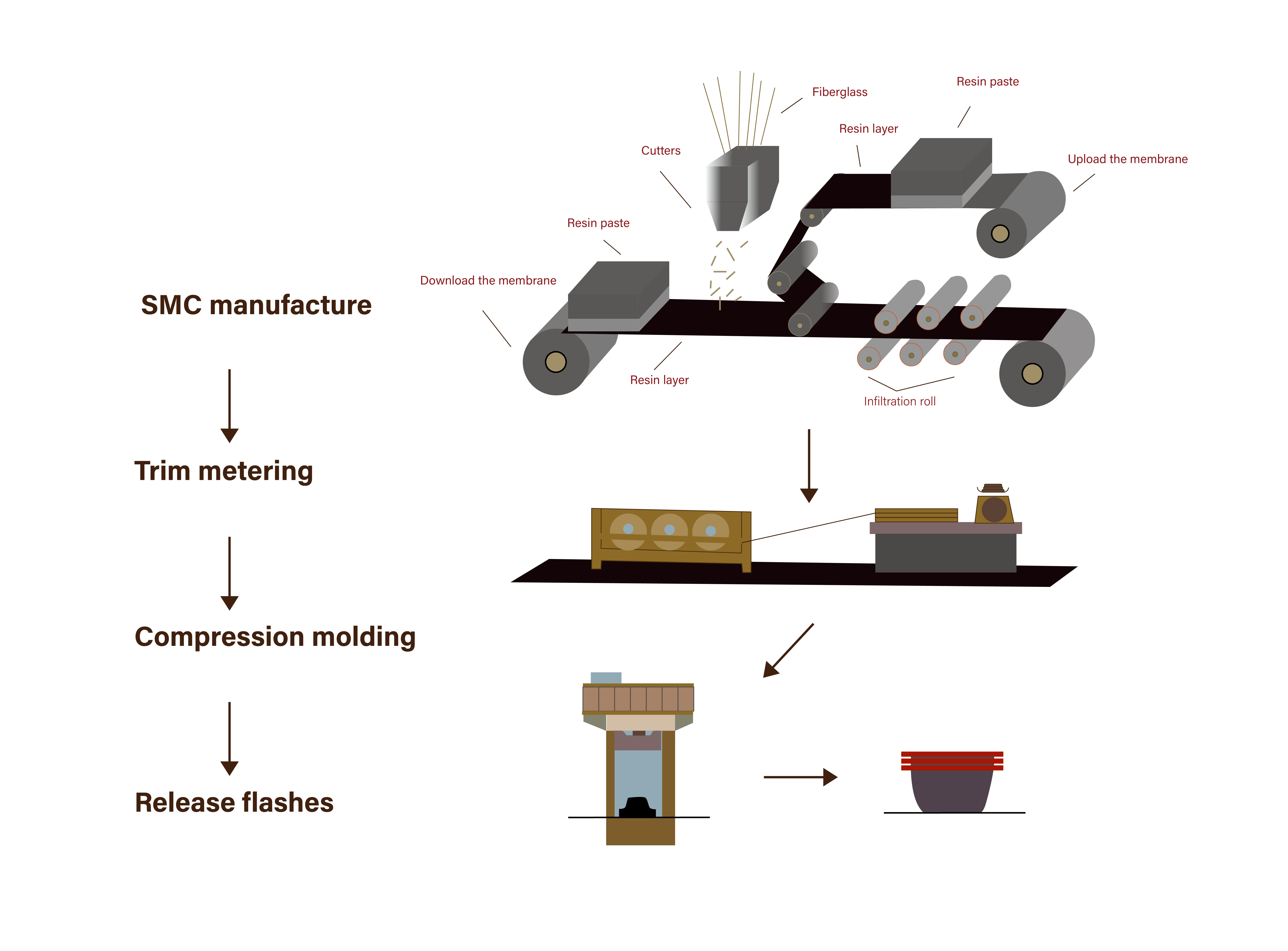
An SMC mold is a production tool designed to form and cure Sheet Molding Compound through compression molding. The mould provides the required product geometry while the molding process applies controlled pressure and heat to form the composite material.
Depending on the product, an SMC mould may include a cavity, core, inserts, parting surfaces, heating components, venting features, locating systems, and structural supports.
A production-grade SMC tool must be designed to maintain its geometry during repeated molding cycles. It should also provide suitable conditions for material flow and curing while allowing the finished part to be released efficiently.
For this reason, the main engineering objectives of SMC tooling include:
SMC molding combines material flow, compression, heating, and curing in a relatively short production cycle. A change in one tooling parameter can influence several aspects of the process at the same time.
For example, unsuitable cavity geometry may restrict material flow, while poor venting can contribute to trapped air. Uneven mould temperature may result in inconsistent curing, and inaccurate parting surfaces can increase flash.
This means that an SMC mould should be developed as part of the complete molding system rather than designed only according to the finished product shape.
A well-engineered mould helps create a more predictable relationship between:
The design of an SMC tool should begin with the product, material, molding process, and production requirements. Several tooling factors require particular attention.
The cavity and core define the final geometry of the SMC component. Critical dimensions, transition areas, ribs, bosses, holes, mounting points, and other functional features should be considered during tooling design.
For large SMC components, maintaining stable geometry across the entire mould surface is especially important because relatively small deviations can affect the final part dimensions.
The parting line determines where the mould sections separate. Its location affects material flow, flash formation, trimming requirements, and demoulding.
A properly designed parting surface helps control material leakage while providing a practical separation path for the finished component.
Draft angles provide clearance between the molded component and the mould surface during demoulding. Insufficient draft can increase release resistance and potentially damage the part or mould surface.
Draft requirements depend on product geometry, surface condition, material characteristics, and the specific SMC moulding process.
The tooling structure must withstand repeated mechanical and thermal loading without excessive deformation.
Adequate rigidity is particularly important for large-area SMC tooling where cavity deformation can affect dimensional accuracy and parting-line performance.
Material flow is one of the central considerations in SMC compression molding. During mould closing, the material charge spreads through the cavity and must reach the required areas before the curing process progresses too far.
The mould design therefore needs to work together with charge size, charge location, product geometry, molding pressure, and temperature.
Poorly planned material flow may contribute to:
For complex SMC components, the charge layout and mould geometry should be evaluated together rather than independently.
The initial position of the SMC charge influences the distance and direction that the material must travel during compression. A suitable charge layout can help shorten unnecessary flow paths and improve material distribution.
The optimal configuration depends on the product geometry and material system, so tooling decisions should be based on the actual application rather than a fixed general rule.
Temperature control is one of the most important functions of an SMC mould. SMC materials require controlled heating during the molding and curing process, and the mould should provide sufficiently stable thermal conditions across the forming area.
Temperature imbalance can contribute to differences in material flow and curing between different areas of the part.
Potential effects include:
For large SMC tooling, heating elements or heating channels should be arranged according to cavity geometry and expected thermal requirements.
The objective of an SMC heating system is not simply to increase mould temperature. It should create repeatable thermal conditions across the areas where the material is formed and cured.
Thermal performance should be evaluated during tooling development and trial molding so that potential hot spots or cold areas can be identified before regular production.
Air trapped between the SMC charge and mould surface can become a potential source of molding defects. Effective venting provides pathways for air and gases to escape during compression.
Venting locations should be determined according to product geometry, material flow, cavity depth, parting-line configuration, and areas where air may become trapped.
Insufficient venting may contribute to:
However, venting must also be controlled so that excessive material leakage does not create unnecessary flash.
For this reason, venting and flash control should be considered together during SMC mold design.
Flash occurs when excess SMC material escapes through the mould parting surfaces during compression. A certain amount of flash may be expected in some applications, but excessive flash increases trimming requirements and can affect production efficiency.
Flash performance is influenced by several factors:
A precision SMC compression mould should provide stable parting surfaces and sufficient structural support to maintain consistent mould closure.
It is also important to recognize that flash is not controlled by tooling alone. Material loading and molding parameters can have a significant influence on the final result.
For visible SMC components, mould surface quality can have a direct influence on the appearance of the finished product.
The cavity surface may transfer machining marks, scratches, polishing defects, or other imperfections to the molded part. This makes surface preparation an important stage of SMC mould manufacturing.
Typical finishing operations may include:
The required cavity finish should be defined according to the product appearance, material system, and production requirements.
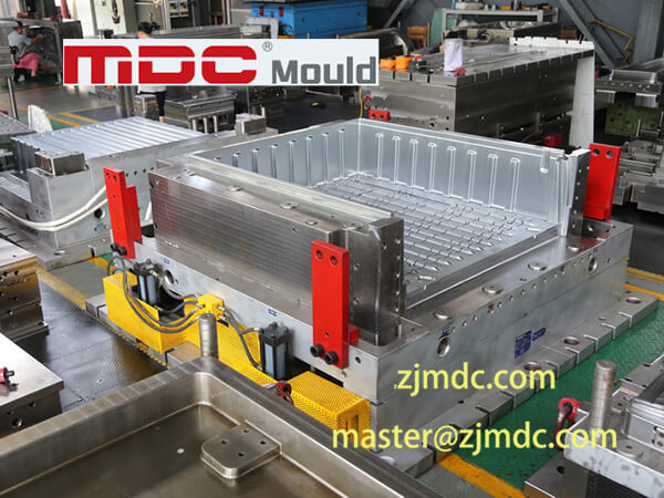
Dimensional accuracy is a fundamental requirement for SMC tooling. The mould should reproduce the approved product geometry consistently over repeated molding cycles.
Several factors can influence dimensional performance:
For this reason, dimensional control should not stop at machining. Tool inspection and trial molding are important for verifying whether the mould performs as expected under actual production conditions.
| SMC Molding Problem | Potential Cause | Tooling Consideration |
|---|---|---|
| Incomplete Filling | Unsuitable charge placement, restricted material flow, or insufficient process conditions | Review cavity geometry, charge layout, flow paths, and venting |
| Excessive Flash | Parting-line clearance, material loading, pressure, or mould wear | Improve parting surfaces and review mould structure and process conditions |
| Surface Defects | Cavity finish, trapped air, contamination, or unstable processing | Improve polishing, venting, cleaning, and process stability |
| Warping | Uneven curing, thermal imbalance, geometry, or residual stress | Review thermal distribution and mould structure |
| Dimensional Variation | Thermal effects, mould deformation, material shrinkage, or machining deviation | Improve dimensional control, structural rigidity, and process stability |
| Difficult Demoulding | Insufficient draft, adhesion, or unsuitable cavity geometry | Review draft, surface finish, and demoulding conditions |
A molding defect should not automatically be attributed to the SMC mold. Material characteristics, press performance, charge weight, charge location, molding pressure, temperature, curing time, and other process variables can also influence the final part.
Manufacturing a precision SMC mold requires coordination between tooling design, machining, finishing, assembly, inspection, and trial production.
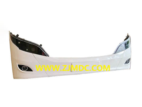
SMC compression molding is used for a wide range of components where repeatable geometry, mechanical performance, electrical properties, corrosion resistance, or weight reduction are required.
MDC manufactures SMC tooling for applications including:
The tooling design is adapted to the geometry, material, molding process, production volume, and quality requirements of each application.
The terms SMC mold, SMC mould, SMC tool, and SMC tooling are often used interchangeably in the composite manufacturing industry.
In practical manufacturing communication, they generally refer to tooling used to form SMC materials through compression molding.
The spelling difference between mold and mould is primarily regional. “Mold” is more common in American English, while “mould” is widely used in British English and many international manufacturing markets.
Similarly, “SMC tooling” can describe the complete tooling solution, while “SMC mold” or “SMC mould” often refers more specifically to the forming tool.
For engineering and purchasing purposes, the important consideration is not the terminology but whether the tooling is designed correctly for the intended SMC molding process.
Choosing an SMC mold manufacturer should involve more than comparing tooling prices. The supplier should understand how mould design affects material flow, curing, surface quality, dimensional accuracy, and production efficiency.
Important factors include:
A capable tooling manufacturer should be able to connect mould design decisions with actual production requirements instead of treating the mould as an isolated machined component.
Providing complete technical information helps the tooling manufacturer develop an SMC tool that matches the intended production process.
Customers should ideally provide:
If some process parameters are not finalized, the tooling configuration can be evaluated based on the available product information and expected manufacturing conditions.
MDC manufactures customized SMC molds, SMC moulds, SMC tools, and SMC tooling for a broad range of composite applications.
Our tooling development integrates product analysis, DFM, mould structure design, precision machining, surface finishing, assembly, dimensional inspection, and trial validation.
This production-oriented approach helps ensure that the mould is developed around the actual requirements of the SMC molding process rather than only the nominal product geometry.
Mould geometry, parting lines, draft, inserts, venting, heating, and structural support are evaluated according to the specific application.
Precision machining establishes the required cavity geometry, while subsequent grinding and polishing prepare critical surfaces for production.
SMC tooling is designed with repeated production cycles in mind, including dimensional stability, thermal conditions, flash control, and demoulding performance.
MDC provides tooling solutions for different SMC applications rather than relying on a single standardized mould configuration.
An SMC mold is a tooling system used to form and cure Sheet Molding Compound through compression molding. It defines the product geometry and influences material flow, curing, surface quality, dimensional accuracy, flash, and demoulding.
SMC tooling refers to the mould and associated tooling components used for SMC compression molding. Depending on the application, the tooling may include cavities, cores, inserts, heating systems, venting features, parting surfaces, and structural supports.
There is generally no technical difference. “Mold” is the American English spelling, while “mould” is commonly used in British English and international manufacturing markets.
An SMC tool is a production tool designed to form SMC material under controlled compression, heat, and curing conditions. The term is often used interchangeably with SMC mold or SMC mould.
Temperature affects material flow and curing behavior during SMC molding. Stable thermal conditions across the mould help improve process consistency and reduce the risk of uneven curing and dimensional variation.
Venting provides pathways for air and gases to escape during compression. Proper venting can help reduce air entrapment, voids, and surface defects.
Flash can be influenced by parting-line accuracy, mould rigidity, material loading, molding pressure, material flow, and mould wear. Tooling design and process control should be considered together.
Yes. MDC manufactures customized SMC molds according to product geometry, material, molding process, production volume, equipment conditions, surface requirements, and customer specifications.
SMC molds are used in automotive, electrical, sanitaryware, transportation, industrial equipment, and other composite manufacturing applications.
Yes. MDC manufactures customized compression moulds for both SMC and BMC applications, with tooling designs adapted to the characteristics and production requirements of each material system.
A high-quality SMC mold is not simply a machined cavity. It is an engineered production system in which geometry, mould rigidity, temperature control, material flow, venting, flash management, surface finish, and demoulding all work together.
The correct tooling configuration depends on the product, SMC material, molding equipment, production volume, and required quality. For this reason, SMC tooling should be developed according to the actual manufacturing process rather than through a one-size-fits-all approach.
At MDC, we manufacture SMC molds, SMC moulds, SMC tools, SMC tooling, and customized compression moulds for automotive, electrical, sanitaryware, industrial, and other composite applications.
From DFM and mould design to CNC machining, polishing, assembly, inspection, and trial molding, MDC focuses on tooling solutions that support stable production and consistent SMC part quality.
Contact MDC to discuss your SMC mold or SMC tooling project.
Contact US
Email: master@zjmdc.com
Tel: +86 576 84616076
Fax: +86 576 84616079
Mobile: +86 13906573507(Mr. Wang)
Address: No.116 mochuang road, Huangyan Xinqian street,Taizhou,Zhejiang,China