
Specialize in Compression molds
Specialize in Compression molds
Thermoplastic composites are gaining attention in automotive and industrial manufacturing because they combine fiber reinforcement with polymer matrices that can soften when heated and solidify when cooled. Depending on the material system and component design, these composites can support lightweight structures, integrated part architectures, automated production, and material recovery.
However, the industrialization of thermoplastic composites requires more than selecting a suitable resin and reinforcement. Manufacturers must coordinate material preparation, heating, forming, consolidation, cooling, dimensional control, and production automation. The tooling system must be designed around these requirements from the beginning.
For composite mold manufacturers such as MDC, the engineering challenge is to translate material and component requirements into tooling that supports repeatable forming conditions, reliable part quality, and practical production efficiency.
This article examines how thermoplastic composite molding works, what differentiates it from thermoset composite processing, and how tooling design influences the transition from material development to scalable automotive manufacturing.
Thermoplastic composite molding is a family of manufacturing processes used to form fiber-reinforced thermoplastic materials into finished components. The material typically consists of a thermoplastic polymer matrix reinforced with glass fiber, carbon fiber, or another suitable reinforcement.
Unlike thermoset matrices that undergo an irreversible curing reaction during processing, thermoplastic matrices can generally be softened through heating and solidified through cooling. The specific processing window depends on the polymer, reinforcement architecture, component geometry, and selected manufacturing process.
Common thermoplastic matrix materials include:
These matrices can be combined with short fibers, continuous fibers, woven fabrics, nonwoven mats, or other reinforcement architectures. The resulting material form determines how it should be heated, positioned, consolidated, and formed inside the tooling.
Thermoplastic and thermoset composites are not competing material categories in every application. Each has specific advantages, processing requirements, and limitations. The appropriate choice depends on the part's structural function, production volume, operating environment, cost target, and end-of-life strategy.
| Comparison Factor | Thermoplastic Composites | Thermoset Composites |
|---|---|---|
| Matrix behavior | Softens when heated and solidifies when cooled, subject to polymer characteristics | Typically forms a crosslinked network during curing |
| Primary process requirement | Heating, forming, consolidation, and controlled cooling | Material flow, mold heating, curing, and controlled demolding |
| Cycle-time considerations | Can support short cycles, depending on heating and cooling requirements | Cycle time depends on cure kinetics, part thickness, and thermal management |
| Joining options | Some compatible systems can be welded or thermally joined | Adhesive bonding and mechanical fastening are common options |
| Reprocessing potential | Some material streams can be remelted and reprocessed, although properties may change | Conventional remelting is generally not possible after crosslinking |
| Tooling priorities | Temperature uniformity, consolidation, cooling, and dimensional stability | Temperature control, material flow, venting, curing, and flash control |
Thermoplastic processing does not automatically guarantee lower production costs or easier recycling. Heating energy, cooling time, equipment investment, material price, fiber architecture, and component complexity can significantly influence the final economics.
Similarly, a thermoset composite may remain the better solution when its established material properties, processing route, certification history, or structural performance better fit the application.
Automotive manufacturers face several simultaneous requirements: reducing vehicle mass, maintaining structural performance, increasing manufacturing throughput, integrating multiple functions, and controlling total component cost.
Thermoplastic composites can contribute to these objectives when material selection and component design are aligned with the intended production system.
Fiber reinforcement allows engineers to tailor mechanical performance through material selection, fiber orientation, local reinforcement, and component geometry.
Instead of replacing a metal component on a weight basis alone, engineers need to compare the complete component architecture. Rib geometry, local thickness, mounting features, load paths, joining methods, and manufacturing constraints all influence whether a composite solution provides a meaningful advantage.
For structural automotive applications, the design must be validated against the actual load cases, impact requirements, fatigue conditions, and environmental exposure.
Thermoplastic composite parts may integrate mounting features, ribs, local reinforcement, and selected joining features into a consolidated component.
Where the design allows multiple parts or operations to be combined, functional integration may reduce assembly work and the number of separate components. However, this benefit depends on the component architecture and whether the integrated design remains practical to mold, inspect, and repair.
Thermoplastic processes can be suitable for applications requiring repeatable cycles and automated material handling. Depending on the material form, production may involve preheating, compression molding, injection molding, overmolding, or a combination of processes.
For high-volume programs, tooling must support the intended cycle sequence and maintain part consistency over repeated production cycles. The mold concept should therefore be evaluated against the target output, equipment layout, and inspection requirements before production tooling is finalized.
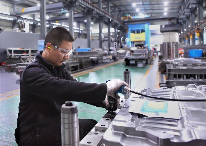
Different thermoplastic composite materials require different processing routes. The choice of process determines how the material enters the mold, how reinforcement is distributed, and which tooling features are necessary.
In thermoplastic compression molding, a prepared charge or preheated composite blank is placed in a mold and formed under pressure. The material must reach a suitable processing condition before or during forming, depending on the selected process.
The tooling then applies the required forming pressure and supports consolidation. Cooling must be managed before the part can be removed while maintaining the required geometry.
Important tooling considerations include:
Thermoplastic compression molding is particularly relevant when a component requires a relatively large projected area, reinforced sheet material, or a geometry that benefits from compression forming.
Injection molding is commonly used for thermoplastic materials containing short fibers or other suitable reinforcement forms. The material is plasticized and injected into a closed mold cavity.
For reinforced materials, mold design must account for gate position, runner configuration, filling behavior, fiber orientation, pressure drop, cooling, and shrinkage.
Injection molding may also be combined with other processes to integrate features into a larger component. The appropriate approach depends on the required structural performance, reinforcement architecture, production volume, and component design.
Overmolding can combine different materials or manufacturing stages within one component architecture. For example, a preformed composite substrate may be combined with an injected thermoplastic feature when the materials and interface are compatible.
This approach can reduce separate assembly operations, but it introduces additional engineering requirements. The tooling must accommodate the substrate, maintain its position, manage local temperatures, and ensure the injected material reaches the intended regions.
Interface strength, differential shrinkage, thermal expansion, and dimensional consistency should be validated during development.
Continuous-fiber thermoplastic laminates and organosheets can provide high directional stiffness and strength. Depending on the material system, they may be heated and formed before additional features are integrated through overmolding or another compatible process.
Unlike short-fiber materials, continuous-fiber reinforcement places greater constraints on deformation. Fiber wrinkling, local stretching, bridging, and orientation changes must be considered during part and tooling design.
The forming strategy should therefore be developed around the actual reinforcement architecture rather than treating every thermoplastic composite as a freely flowing material.
Recycled carbon fiber is attracting interest as manufacturers seek to recover value from production scrap and end-of-life composite components.
Recovered fibers may be converted into chopped-fiber compounds, nonwoven mats, or other reinforcement formats. These materials can then be considered for selected thermoplastic or thermoset applications, depending on their properties and processing requirements.
Recycled carbon fiber can support material-efficiency objectives, but its suitability depends on fiber length, surface condition, residual matrix, contamination, orientation, and the mechanical performance required from the finished part.
The mechanical performance of a recycled-fiber composite depends on the recovery method and subsequent material processing. Fiber shortening, surface changes, contamination, and differences in reinforcement distribution can influence final part properties.
Therefore, a recycled carbon fiber material should be qualified for its intended application rather than assumed to perform identically to a virgin continuous-fiber reinforcement.
A recycled carbon fiber compound containing short fibers may be processed differently from a nonwoven mat or a continuous-fiber thermoplastic laminate.
For compression molding, the initial charge form and placement influence material distribution and local reinforcement concentration. For injection molding, gate design and flow conditions can influence fiber orientation and mechanical anisotropy.
Tooling development should consider the actual material format, not merely the fact that the reinforcement is recycled carbon fiber.
Thermoplastic matrices can often be softened and reshaped, but this does not mean that every finished composite component can be recycled indefinitely without performance loss.
Repeated heating, fiber damage, contamination, incompatible materials, coatings, adhesives, and mixed-material assemblies may reduce the value of recovered material or complicate processing.
A practical circular manufacturing strategy should consider material identification, component disassembly, scrap collection, separation, reprocessing, quality control, and the availability of suitable end markets.
Tooling engineers can contribute by supporting designs that minimize unnecessary material waste, enable consistent manufacturing, and avoid process features that make the intended recovery route unnecessarily difficult.
Thermoplastic composite tooling must be designed around the material's temperature-dependent behavior, reinforcement architecture, and forming process.
The central challenge is to create a mold that supports the required geometry while allowing the material to be heated, formed, consolidated, cooled, and demolded consistently.
| Engineering Factor | Potential Manufacturing Challenge | Tooling Design Consideration |
|---|---|---|
| Material temperature | Incomplete forming or inconsistent consolidation | Heating strategy, temperature measurement, thermal uniformity |
| Charge placement | Uneven filling or reinforcement distribution | Charge location, locating features, cavity geometry |
| Continuous-fiber architecture | Wrinkling, bridging, or fiber misalignment | Forming surfaces, radii, preform support, local geometry |
| Material consolidation | Voids, incomplete contact, or inconsistent thickness | Pressure distribution, venting, mold closure, process sequence |
| Cooling behavior | Warpage, shrinkage variation, residual stress | Cooling layout, thermal balance, dimensional compensation |
| Part removal | Distortion or damage during demolding | Draft, ejector layout, release strategy, handling sequence |
| Reinforced material wear | Surface degradation after repeated cycles | Tool steel, surface treatment, wear-critical inserts |
| Production automation | Inconsistent loading or handling interference | Locating features, robot access, transfer clearances, cycle integration |
These factors should be evaluated together. A change to the heating strategy, for example, may influence material viscosity, forming behavior, cooling time, and final dimensions. Tooling optimization therefore requires a system-level view.
Thermal management is one of the most important considerations in thermoplastic composite molding.
The material must reach the required forming temperature, and the mold must support the intended consolidation process. The part must then cool sufficiently to retain its geometry during demolding and subsequent handling.
Uneven heating can cause different regions of a charge to exhibit different forming behavior. Some areas may become sufficiently soft while other regions remain too stiff for the intended process.
For complex tooling, temperature distribution can be influenced by wall thickness, mold mass, channel layout, inserts, local geometry, and the selected heating system.
The engineering target should be established from the material supplier's processing recommendations and validated through temperature measurement and molding trials.
Cooling is not simply the final step after forming. It can determine the overall cycle time and influence the dimensions of the finished part.
If cooling is uneven, different regions may contract at different rates. This can contribute to warpage, residual stress, or dimensional variation.
A practical cooling strategy should consider:
Reducing cycle time without considering dimensional stability may simply transfer the problem to inspection, rework, or assembly. The objective is to shorten the cycle while maintaining the required quality.
In thermoplastic composite compression molding, pressure helps bring the material into contact with the mold surface and supports consolidation. The appropriate pressure sequence depends on the material, reinforcement form, part geometry, and equipment.
Insufficient consolidation may result in voids or incomplete contact between material layers. Excessive or poorly controlled pressure can contribute to material displacement, reinforcement distortion, flash, or unnecessary mold loading.
Air evacuation must also be considered. Air trapped between the charge and mold surface, or between material layers, can affect surface quality and internal integrity.
Tooling solutions may include appropriately positioned vents, carefully designed closing sequences, controlled pressure application, and vacuum assistance where the process and mold configuration justify it.
Vacuum should not be treated as a universal solution. Its effectiveness depends on the material architecture, air escape paths, tooling sealing, process sequence, and the nature of the defect being addressed.
Dimensional stability is especially important for automotive components that must fit with metal structures, injection-molded parts, interior trim, or other composite components.
Warpage can result from several interacting mechanisms:
Not every dimensional problem can be corrected by changing the mold cavity. Engineers should distinguish between geometry-related errors, process variation, material behavior, and measurement or fixture effects.
Effective warpage control may involve coordinated changes to component geometry, reinforcement layout, thermal management, tooling stiffness, cooling strategy, and process parameters.
Some automotive thermoplastic composite components combine compression molding with injection molding or overmolding. This can enable a reinforced substrate to be formed while selected mounting features, ribs, clips, or functional details are produced through an additional molding stage.
Integration can reduce separate assembly operations, but it also introduces interface and process-control challenges.
The most efficient integrated process is not necessarily the one with the fewest individual operations. It is the one that meets quality and throughput targets with acceptable equipment complexity, maintenance requirements, and total manufacturing cost.
For high-volume automotive programs, automation can improve loading consistency, cycle repeatability, handling efficiency, and production traceability.
However, automation must be incorporated into the tooling concept early enough to avoid conflicts between the mold, robot, material transfer system, and inspection equipment.
Tooling development should evaluate:
Repeatability also depends on consistent incoming materials and stable processing conditions. Automation cannot fully compensate for uncontrolled material temperature, variable charge dimensions, or a poorly designed forming sequence.
When a thermoplastic composite component fails to meet its requirements, the investigation should connect the observed defect with material characteristics, process history, and tooling behavior.
| Observed Problem | Possible Causes | Recommended Investigation |
|---|---|---|
| Incomplete forming | Insufficient material temperature, unsuitable charge geometry, restricted flow | Review material preparation, heating, charge placement, and cavity geometry |
| Internal voids | Entrapped air, inadequate consolidation, moisture or material-related issues | Review material conditioning, air evacuation, pressure sequence, and consolidation |
| Warpage | Uneven cooling, asymmetric reinforcement, residual stress | Review cooling layout, part architecture, fiber orientation, and process consistency |
| Surface defects | Contamination, trapped air, material degradation, poor mold-surface condition | Inspect material handling, thermal history, venting, and mold finish |
| Fiber misalignment | Excessive deformation, unsuitable forming sequence, material movement | Review reinforcement architecture, preform design, radii, and forming strategy |
| Dimensional inconsistency | Variable material condition, thermal imbalance, mold deflection | Compare process records, mold temperatures, dimensions, and fixture conditions |
| Excessive cycle time | Slow heating or cooling, manual handling, unnecessary process steps | Review thermal design, automation, transfer sequence, and process integration |
| Premature tooling wear | Abrasive reinforcement, unsuitable material selection, inadequate maintenance | Inspect wear-critical areas and review tool steel, surface treatment, and production conditions |
These are possible causes rather than universal diagnoses. Root-cause analysis should be based on the actual material specification, process data, defect location, and inspection results.
A prototype mold and a production mold may have similar cavity geometry, but their engineering priorities can differ significantly.
Prototype tooling may prioritize design verification and development flexibility. Production tooling must also support cycle-time targets, repeatability, automation, maintenance, and long-term dimensional consistency.
For thermoplastic composite applications, production tooling should be evaluated across several dimensions.
The tooling team needs the component geometry, material grade, reinforcement architecture, target properties, production volume, and inspection requirements. These inputs establish the starting point for the mold concept.
The mold must match the available press, heating system, cooling system, material-loading method, and any integrated injection or handling equipment.
Tooling stiffness, thermal distribution, cooling strategy, and dimensional compensation should be considered together. The design must remain functional under the expected operating conditions.
Trials should verify material forming, surface quality, dimensional accuracy, cycle sequence, and repeatability. For demanding applications, additional structural, environmental, or durability testing may be necessary.
Wear-critical areas, replaceable inserts, cleaning access, and routine inspection requirements should be considered before the mold enters serial production.
MDC focuses on composite mold engineering and manufacturing for industrial applications. Its tooling approach considers the relationship between part geometry, material behavior, process requirements, mold construction, and production equipment.
For thermoplastic composite projects, the specific tooling concept must be developed according to the selected material and forming route rather than applying a standard thermoset mold design without modification.
Relevant engineering considerations may include:
MDC's manufacturing resources include FIDIA five-axis CNC machining and large-format tooling manufacturing capabilities. For suitable projects, machining dimensions can reach approximately 6 × 4 meters, subject to the specific tooling configuration and manufacturing requirements.
Project feasibility should be confirmed against the required mold structure, material system, press specifications, heating and cooling requirements, and target production process.
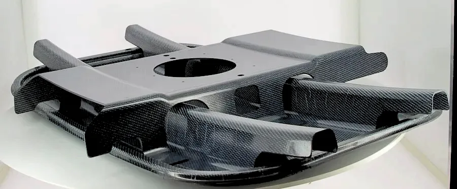
To develop a practical tooling proposal, buyers should provide sufficient information to connect the part requirements with the manufacturing process.
For recycled-fiber materials, it is also useful to provide available material data, including fiber characteristics, processing recommendations, and relevant mechanical test results.
These inputs help the tooling team determine whether compression molding, injection molding, overmolding, or a combined process is the most appropriate manufacturing route.
The development of thermoplastic composites is closely linked to advances in material engineering, forming technology, automation, and recycling infrastructure.
Several trends are particularly relevant to industrial tooling development:
These developments do not eliminate the need for thermoset composites. Instead, they expand the range of manufacturing options available to engineers.
The long-term opportunity lies in selecting the appropriate material and process for each application, then developing tooling that can deliver the required quality and output consistently.
Thermoplastic composite molding is a manufacturing process that forms fiber-reinforced thermoplastic materials into components using suitable heating, forming, consolidation, and cooling conditions. The exact process depends on the polymer matrix, reinforcement architecture, and component geometry.
Thermoplastic matrices can generally be softened by heating and solidified by cooling, while thermoset matrices form an irreversible crosslinked structure during curing. Their processing methods, joining options, and end-of-life recovery routes therefore differ.
Common processes include compression molding, injection molding, overmolding, and forming of continuous-fiber thermoplastic laminates. The appropriate process depends on material form, component geometry, structural requirements, production volume, and equipment availability.
Some thermoplastic composite materials can be mechanically reprocessed or remelted, but their recovery potential depends on the polymer, reinforcement, contamination, material degradation, and product architecture. Recycling does not guarantee that the recovered material will retain its original properties.
Yes. Recycled carbon fiber can be incorporated into suitable thermoplastic compounds, mats, and other reinforcement formats. The resulting material must be evaluated for fiber characteristics, processability, and application-specific mechanical requirements.
Cooling affects cycle time, shrinkage, residual stress, demolding, and dimensional stability. Uneven cooling can cause warpage or inconsistent dimensions, so the cooling strategy should be developed together with the mold geometry and material specification.
Possible causes include uneven cooling, directional shrinkage, asymmetric fiber orientation, local thickness differences, residual stress, and inconsistent processing conditions. Effective correction requires identifying the dominant cause rather than changing the mold geometry alone.
Yes. Some manufacturing systems combine compression molding of a reinforced substrate with injection molding or overmolding of additional features. Successful integration depends on substrate positioning, material compatibility, thermal conditions, interface performance, and process synchronization.
Important factors include material temperature, charge placement, reinforcement architecture, mold stiffness, heating and cooling, consolidation, venting, dimensional stability, demolding, automation, and maintenance. The design must match the actual material and production route.
Key inputs include CAD data, material and reinforcement specifications, target production volume, dimensional and performance requirements, press specifications, cycle-time targets, heating and cooling requirements, automation needs, and validation criteria.
Thermoplastic composites offer manufacturers opportunities to combine lightweight design, functional integration, automated processing, and selected material recovery strategies. However, these advantages are only realized when material selection, component design, manufacturing processes, and tooling are developed as an integrated system.
For automotive and industrial applications, the key engineering priorities are predictable material forming, uniform thermal management, effective consolidation, dimensional stability, repeatable production, and compatibility with the intended end-of-life strategy.
Successful thermoplastic composite manufacturing depends not only on the material itself, but also on how effectively the tooling converts material potential into reliable production performance.
Contact MDC about composite tooling projects through engineering-led mold development, precision manufacturing, and consideration of the process requirements that influence production quality and consistency.
Contact US
Email: master@zjmdc.com
Tel: +86 576 84616076
Fax: +86 576 84616079
Mobile: +86 13906573507(Mr. Wang)
Address: No.116 mochuang road, Huangyan Xinqian street,Taizhou,Zhejiang,China