
Specialize in Compression molds
Specialize in Compression molds
Automotive lightweighting is no longer limited to replacing steel with a single alternative material. Engineers increasingly evaluate the complete material system: reinforcement fiber, resin matrix, fiber architecture, part geometry, manufacturing process and tooling requirements.
This is particularly important for automotive composite materials. Glass fiber, carbon fiber, basalt fiber and natural fiber can all reinforce polymer matrices, but they do not provide the same combination of stiffness, strength, weight, cost, surface quality, processability or production efficiency.
For manufacturers, the practical question is therefore not simply “Which fiber is strongest?”. The more useful engineering question is:Which material system and manufacturing route can produce the required automotive part consistently at the required production volume?
This article explains the relationship between fiber selection, resin systems, reinforcement architecture, automotive manufacturing processes and tooling considerations. The objective is to provide a practical framework for evaluating fiber reinforced composites for automotive applications.
A composite part is not defined by its reinforcement fiber alone. Its final performance depends on how the reinforcement and matrix work together and how the material is processed into the finished geometry.
A simplified composite material system can be considered as:
Changing one of these elements can affect the others. For example, a continuous-fiber composite may provide excellent directional stiffness, but its material placement and tooling requirements can be significantly different from a short-fiber compression-molded material.
Similarly, a material that performs well in a laboratory coupon test may not automatically be the most suitable choice for a high-volume automotive component. Production cycle time, fiber orientation, mold filling, dimensional stability, joining requirements and cost must also be considered.
This is why automotive composite material selection should begin with the part function and manufacturing strategy, rather than starting with a fiber name.

Several reinforcement systems can be used in automotive composite manufacturing. Their roles are different, and no single fiber type is optimal for every application.
Glass fiber is one of the most widely used reinforcements for automotive composites because it provides a practical balance between mechanical performance, material cost and manufacturing flexibility.
Glass fiber can be supplied in different forms, including chopped fibers, continuous rovings, woven fabrics, mats and engineered reinforcement structures. These forms support different manufacturing processes.
In automotive applications, glass fiber reinforced materials can be used for body panels, structural covers, underbody components, battery-related components, front-end structures and other parts where weight reduction must be balanced with cost and production requirements.
SMC, GMT and LFT are particularly important material routes when glass fiber reinforcement is combined with production-oriented automotive molding processes.
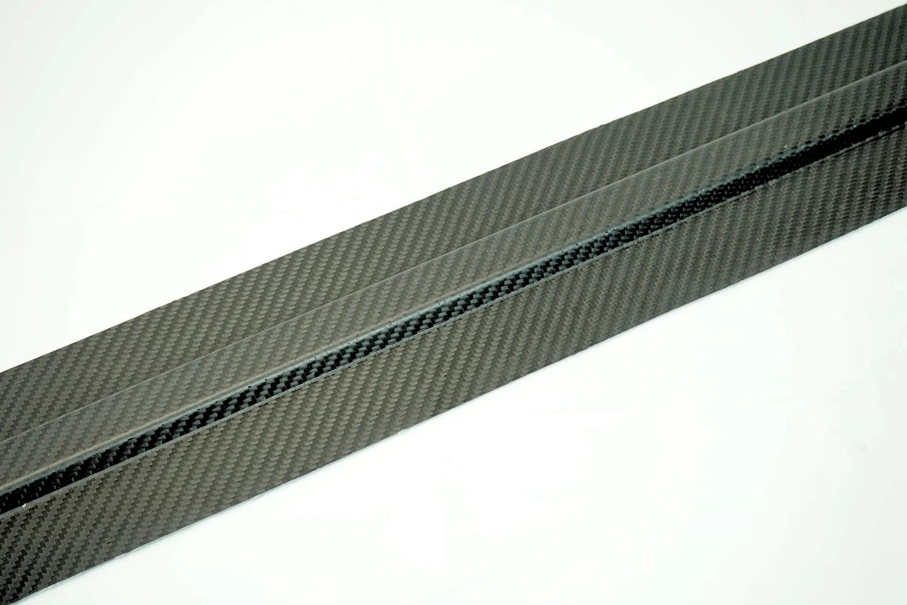
Carbon fiber provides high specific stiffness and strength and is therefore attractive for applications where weight reduction has a high structural value.
Compared with conventional glass fiber systems, carbon fiber composites can provide a different balance of stiffness, density and directional mechanical performance. However, the material itself is only one part of the engineering decision.
Carbon fiber composites may be manufactured using prepreg, RTM, compression molding and other processes. The appropriate route depends on part geometry, fiber architecture, production volume, performance targets and cost requirements.
For automotive production, carbon fiber SMC and other compression-molded carbon fiber systems demonstrate that carbon fiber does not necessarily mean manually laid-up fabric or autoclave production.
Basalt fiber is produced from basalt rock and can be used as reinforcement in thermoplastic or thermoset composite systems.
Automotive applications remain more application-specific than mainstream glass fiber systems, but basalt fiber is of interest where engineers are evaluating alternative reinforcement materials with particular mechanical, thermal or material-cost characteristics.
Depending on the material system, basalt fiber may be supplied as chopped fiber, continuous reinforcement, fabric or other forms before being combined with a polymer matrix.
Natural fibers such as flax and kenaf can be combined with thermoplastic or thermoset matrices for selected automotive interior and semi-structural applications.
Their attraction is not based only on weight. Material sourcing, renewable content, surface appearance and the possibility of reducing dependence on fossil-based reinforcement materials can also influence material selection.
However, natural fibers introduce their own manufacturing considerations. Moisture content, fiber treatment, thermal exposure and dimensional stability must be controlled during processing.
Two automotive composite materials can use the same reinforcement fiber but behave very differently because their fiber architecture and matrix system are different.
Important variables include:
This distinction is especially important in automotive compression molding. A material containing chopped glass fiber does not behave in the same way as a material containing continuous glass fiber.
During molding, reinforcement can move, orient and redistribute. As a result, the final mechanical behavior may depend on the actual flow pattern rather than only on the nominal material specification.
This creates a direct connection between material selection and mold engineering.
SMC, GMT and LFT are often discussed together because all three can be used to produce lightweight automotive components. However, they represent different material and processing strategies.
Sheet Molding Compound combines a thermosetting resin system with chopped reinforcement, fillers and additives to form a sheet-like molding material.
During production, the SMC charge is placed into a heated mold and compressed. The resin system undergoes chemical curing, allowing the material to form a rigid finished component.
SMC is attractive for automotive components requiring relatively complex geometry, dimensional control, integrated ribs and other molded features.
Typical application areas can include:
From a tooling perspective, SMC requires attention to charge placement, flow behavior, venting, shrinkage, draft, parting lines and local reinforcement geometry.
Glass Mat Thermoplastic, or GMT, generally uses a thermoplastic matrix reinforced with glass fiber mat. The material is heated before compression molding and then cooled to establish the final shape.
GMT is commonly associated with automotive semi-structural components where impact performance, weight, productivity and material recyclability considerations can be relevant.
Compared with thermoset SMC, the processing mechanism is different because the thermoplastic matrix softens during heating and solidifies during cooling rather than undergoing irreversible chemical crosslinking during molding.
Long Fiber Thermoplastic materials use relatively long reinforcing fibers in a thermoplastic matrix. Depending on the manufacturing route, LFT can be processed through injection molding or compression-oriented processes.
LFT can provide a useful combination of structural performance and thermoplastic processing efficiency for selected automotive components.
Fiber length retention and orientation are particularly important because the molding process can influence how the reinforcement is distributed inside the finished part.
The distinction between thermoset and thermoplastic matrices is more than a material terminology issue. It changes how the material behaves during processing and therefore influences tooling and production strategy.
| Factor | Thermoset Composite | Thermoplastic Composite |
|---|---|---|
| Basic mechanism | Chemical curing / crosslinking | Heating, melting or softening, then cooling |
| Typical examples | SMC, BMC and many thermoset composites | GMT, LFT and other thermoplastic composites |
| Material behavior during processing | Viscosity and curing change with temperature and time | Viscosity changes with temperature and shear |
| Tooling considerations | Heating, curing, shrinkage and venting | Heating, cooling, flow and dimensional control |
| Production strategy | Compression molding and related processes | Injection, compression and hybrid processes |
This is why a composite mold should not be designed only from the final CAD geometry. The material's processing behavior must be understood before the tooling architecture is finalized.
For a more detailed comparison, see thermoplastic vs. thermoset materials.
Composite materials are often anisotropic. Their mechanical properties can vary significantly depending on the direction of reinforcement.
Continuous fibers provide a clear example. A reinforcement aligned with the principal load direction can contribute substantially to stiffness and strength in that direction, while a different orientation can produce a different structural response.
Chopped-fiber materials behave differently because the fibers can rotate and redistribute during material flow.
This means that engineers should evaluate:
For compression-molded automotive parts, the mold cavity and charge layout influence how material moves before the part reaches its final shape. Therefore, material flow should be considered during tooling design rather than treated only as a production-stage issue.
Lightweighting does not mean simply reducing wall thickness. A composite part can achieve weight reduction by combining material distribution with structural geometry. Learn more about composite part and mold design.
Ribs can increase local stiffness without requiring a uniformly thick wall. However, rib geometry must be compatible with material flow, demolding and local shrinkage behavior.
Curved surfaces can improve stiffness while maintaining relatively low material thickness. The effectiveness of this strategy depends on the material system and the load case.
Holes, fasteners, inserts and attachment points can create local stress concentrations. Composite design therefore requires attention to how loads enter and leave the molded structure.
Abrupt changes in thickness can influence material flow, shrinkage and dimensional stability. A well-designed composite part should therefore balance structural requirements with manufacturing constraints.
The following framework illustrates how different material systems may be considered for different automotive requirements. Actual material selection must be validated against the component's specifications, environment and production process.
| Automotive Application | Potential Composite Route | Primary Engineering Considerations |
|---|---|---|
| Exterior panels | SMC, carbon fiber composites and other molded composites | Surface quality, stiffness, dimensional stability and production volume |
| Battery covers | Glass fiber composites, SMC, thermoplastic composites and other engineered systems | Electrical insulation, thermal exposure, structural protection and fire performance |
| Underbody components | GMT, LFT, SMC and other reinforced polymer systems | Impact, stiffness, environmental exposure and cost |
| Front-end structures | LFT, GMT and other reinforced thermoplastics | Impact behavior, integration, weight and production efficiency |
| Structural carbon fiber parts | Prepreg, RTM, compression molding and carbon fiber SMC | Specific stiffness, directional strength, weight and manufacturing cost |
| Interior components | Natural fiber composites, GMT, LFT and other reinforced polymers | Weight, appearance, acoustic performance and material sustainability |
Browse the full range of automotive compression moulds for more application examples.
One of the most important engineering connections is the relationship between material selection and mold design.
A mold designed for a particular composite process must account for the way the material enters, flows, compresses, cures or cools inside the cavity.
Chopped-fiber SMC, long-fiber thermoplastics and continuous-fiber systems have different flow characteristics. The mold layout, charge position and local geometry therefore need to be considered together, often supported by mold flow analysis.
Thermoset compression molding requires controlled heating to support curing. Thermoplastic compression molding requires controlled heating and cooling to establish the required processing window and dimensional stability.
Air and volatile management become important when material is compressed inside a closed cavity. Venting strategy can affect surface quality, void formation and process consistency.
Composite materials can exhibit process-related dimensional changes. Mold design therefore needs to consider material shrinkage, local thickness, fiber orientation and temperature distribution.
Ribs, deep features, undercuts and complex surface geometry can make demolding more difficult. Draft and parting-line decisions should be made while the part and material system are still being developed. See our notes on demolding challenges.
| Selection Mistake | Why It Creates Problems | Better Engineering Approach |
|---|---|---|
| Choosing fiber only by strength | Ignores processability, cost and geometry | Evaluate the complete material-process-part system |
| Ignoring fiber orientation | Actual part performance may differ from nominal material data | Consider load direction and material flow |
| Designing the mold after freezing the part | Manufacturing constraints may force expensive design changes | Develop part and tooling concepts together |
| Using identical geometry for different materials | Different materials may have different flow and shrinkage behavior | Adapt geometry to the selected process |
| Focusing only on material price | Tooling, cycle time and scrap can dominate total manufacturing cost | Evaluate total production economics |
A practical material selection process can be organized into several engineering stages.
This workflow reduces the risk of selecting a material that performs well in theory but creates unnecessary production difficulties.
For automotive composite components, the boundary between material engineering and tooling engineering is often much smaller than it appears.
Consider a compression-molded part with several ribs and mounting points. The material determines how the charge flows, while the geometry influences that flow. The tooling determines how the material is heated, compressed, vented and released. These factors interact throughout the molding cycle.
Consequently, a tooling engineer should understand more than the final CAD model. Important information includes:
Early communication between material suppliers, part designers and mold manufacturers can therefore reduce late-stage tooling modifications.
Automotive composite tooling is not simply a negative copy of the final component. The mold must accommodate the behavior of the selected material during manufacturing.
This becomes particularly important for large or complex components, where material flow, dimensional stability, heating uniformity and structural rigidity can affect the final result.
MDC approaches composite tooling from this manufacturing perspective. For projects involving SMC, BMC, carbon fiber and other compression-molded composite materials, tooling development can be evaluated together with material behavior, part geometry and production requirements.
MDC's manufacturing capabilities include large-scale CNC machining and high-capacity compression molding support. Its equipment and manufacturing resources are intended for demanding industrial composite tooling projects where mold size, structural rigidity, machining accuracy and trial requirements need to be considered together.
The key objective is not simply to manufacture a mold that matches the CAD model. It is to develop tooling that supports a stable and repeatable production process.
When requesting a quotation for an automotive composite mold, providing material and process information at the beginning can significantly improve the technical evaluation.
If the material is still under evaluation, the mold supplier should also receive the candidate material systems and the reason each one is being considered. This allows tooling feasibility to be considered before the material decision is fully locked.
The development of lightweight automotive components is moving from simple material substitution toward integrated material and manufacturing engineering.
Glass fiber, carbon fiber, basalt fiber and natural fiber can all contribute to automotive lightweighting, but they serve different engineering purposes. More importantly, the fiber itself does not determine the final performance.
Fiber type, matrix, fiber architecture, orientation, part geometry, manufacturing process and tooling must be evaluated as one connected system.
For high-volume automotive production, the most appropriate material is therefore not necessarily the material with the highest laboratory strength. It is the material system that can meet the required performance while remaining manufacturable, dimensionally stable and economically viable at the intended production volume.
This is also why automotive composite material selection should involve tooling engineers early in the development process. A material decision can influence mold design, flow behavior, heating, cooling, venting, demolding and ultimately production consistency.
Automotive composite materials are engineered material systems that combine a reinforcing phase, such as glass fiber, carbon fiber, basalt fiber or natural fiber, with a polymer matrix. The reinforcement provides structural support while the matrix binds and protects the fibers.
Glass fiber is widely used because it provides a practical combination of mechanical performance, cost and processing flexibility. Carbon fiber is selected for applications where high specific stiffness or strength and weight reduction justify its higher material and processing cost.
SMC is generally a thermoset sheet molding compound processed by compression molding. GMT is a glass-mat-reinforced thermoplastic material typically formed by heating, compression and cooling. LFT uses longer reinforcing fibers in a thermoplastic matrix and can be processed through injection or compression-oriented manufacturing routes.
Yes. Carbon fiber can be used in several compression molding routes, including carbon fiber SMC and other engineered composite systems. The appropriate process depends on the required fiber architecture, part geometry, performance and production volume. See also carbon fiber molding.
Fiber orientation influences the direction in which reinforcement contributes most effectively to mechanical performance. In molded composites, material flow can also change fiber orientation, so part geometry, charge placement and tooling design should be considered together.
Material selection affects flow behavior, heating or cooling requirements, shrinkage, venting, draft, demolding and dimensional control. Therefore, composite tooling should be developed according to the selected material and manufacturing process rather than only the final CAD shape.
Natural fiber composites can be suitable for selected automotive interior and semi-structural applications. Moisture content, fiber treatment, thermal stability, dimensional behavior and surface requirements need to be considered during material and process development. See sustainable composite tooling.
Important information includes the part CAD model, material grade, fiber type and content, manufacturing process, production volume, dimensional tolerances, surface requirements, press parameters, heating or cooling requirements and demolding strategy. Contact MDC to discuss a specific tooling project.
Automotive composite materials provide manufacturers with multiple approaches to lightweighting, but successful application depends on more than selecting a high-performance fiber.
The reinforcement, resin matrix, fiber architecture, manufacturing process and tooling must work together. For production components, this integrated approach helps engineers balance weight, structural performance, manufacturability, dimensional accuracy and production economics.
For composite tooling projects, MDC supports the transition from composite part design to production tooling by considering material behavior, molding requirements and tool manufacturing requirements together.
Contact US
Email: master@zjmdc.com
Tel: +86 576 84616076
Fax: +86 576 84616079
Mobile: +86 13906573507(Mr. Wang)
Address: No.116 mochuang road, Huangyan Xinqian street,Taizhou,Zhejiang,China